HI
Input: Pin 24 on main board DB37, PIP from TFI module. Is that the shielded twisted pair on their harness?
thanks
DIY Auto Tune Harness help
Moderators: jsmcortina, muythaibxr
-
the_buster
- Helpful MS/Extra'er
- Posts: 66
- Joined: Sun Jun 01, 2014 12:50 am
DIY Auto Tune Harness help
Last edited by the_buster on Thu Jul 31, 2014 10:55 pm, edited 2 times in total.
-
the_buster
- Helpful MS/Extra'er
- Posts: 66
- Joined: Sun Jun 01, 2014 12:50 am
Re: DIY Auto Tune Harness help
Hi,
Any help here would be great for the most part I think that I have it sorted. I have never worked on car electrics like this before and I am learning heaps.
Here is what I have so far:
STOCK harness: MS3/MS3X
PIN 17: FAN 1 Connected to FIDDLE
PIN 24: Power Ground PIN: 19
PIN 35: HEGO 1 PIN: 23
PIN 38: Engine Coolant Temp PIN: 21
PIN 39: IAT PIN: 20
PIN 49: PIP PIN: 24 (work in progress)
PIN 50: SPOUT PIN: 26 MS3X
PIN 51: Power Ground PIN 18
PIN 61: HEGO2 PIN: ? HEGO2 MS3X
PIN 71: Vehicle power PIN: 28
PIN 76: Power Ground PIN: 17
PIN 77: Power Ground PIN: 16
PIN 80: Fuel Pump PIN: 37
PIN 83: Idle Speed Control PIN: 30
PIN 89: TPS PIN: 22
PIN 90: VREF PIN: 26
PIN 91: Signal Return PIN: 7
PIN 103: Power Ground PIN: 15
I have not set-up injector wiring yet, I still need to map it out with my firing order. The above will be wired in with a DIY Auto Tune harness to the stock harness and eventually give way to full control and a full new harness. I have been a little confused between DIY and the Megamanual. Does the above look good enough to be used? are the connections right to my MS3?
thanks
Re: DIY Auto Tune Harness help
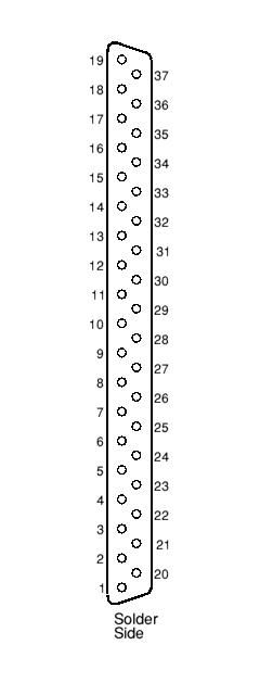
The pin numbers refer to the pin numbers of the DB 37 connector, which are (usually) printed on the body, but can be hard to see. If you remove the cover from the connector, you can check which wire goes to which pin. This may help you identify the number layout - it is the connector viewed from the cable side.the_buster wrote:HI
Input: Pin 24 on main board DB37, PIP from TFI module. Is that the shielded twisted pair on their harness?
thanks
Rover SD1 3.5 EFI
MS2 V3
EDIS
Tech Edge O2
London UK.
MS2 V3
EDIS
Tech Edge O2
London UK.
-
Matt Cramer
- Super MS/Extra'er
- Posts: 17507
- Joined: Thu Apr 16, 2009 8:08 pm
Re: DIY Auto Tune Harness help
Pin 24 goes to the white wire inside the shielded pair.
What do the pin numbers you have that go up to 103 come from?
What do the pin numbers you have that go up to 103 come from?
Matt Cramer -1966 Dodge Dart slant six running on MS3X
-
the_buster
- Helpful MS/Extra'er
- Posts: 66
- Joined: Sun Jun 01, 2014 12:50 am
Re: DIY Auto Tune Harness help
Cheers Mate!Matt Cramer wrote:Pin 24 goes to the white wire inside the shielded pair.
What do the pin numbers you have that go up to 103 come from?
Stock Ford EEC-V ECU, I have a pin out map for the stock ECU but I confirmed it with a factory wiring diagram first. All the info there is accurate.
By the way the stock wiring also has PIP and SPOUT inside a shielded wire as well. For me learning how to read a wiring diagram was a challenge. Mine is the EF model.
thanks.
Pin out Removed.
Last edited by the_buster on Thu Aug 07, 2014 6:03 pm, edited 3 times in total.
-
Matt Cramer
- Super MS/Extra'er
- Posts: 17507
- Joined: Thu Apr 16, 2009 8:08 pm
Re: DIY Auto Tune Harness help
If you want others to weigh in on whether you've matched up the pins correctly, it would help to post the pinout of the ECU you're trying to match.
Matt Cramer -1966 Dodge Dart slant six running on MS3X
-
the_buster
- Helpful MS/Extra'er
- Posts: 66
- Joined: Sun Jun 01, 2014 12:50 am
Re: DIY Auto Tune Harness help
Matt Cramer wrote:If you want others to weigh in on whether you've matched up the pins correctly, it would help to post the pinout of the ECU you're trying to match.
Yeah just did that
Thanks
-
the_buster
- Helpful MS/Extra'er
- Posts: 66
- Joined: Sun Jun 01, 2014 12:50 am
Re: DIY Auto Tune Harness help
Hi all,
Well I'm not a complete idiot. keyed on today and everything worked. referenced for 2 weeks and posted many silly questions
thanks all!
Well I'm not a complete idiot. keyed on today and everything worked. referenced for 2 weeks and posted many silly questions
thanks all!