New owner of a used MS2 V3.0

A general forum and a place for initial or prospective users. See Manuals/Documentation
Click here to enter
Contact a Forum Administrator
If unsure where to post, post in this sub-forum.

Moderators: jsmcortina, muythaibxr

Post Reply
frase29
MS/Extra Newbie
Posts: 5
Joined: Sat Jun 25, 2016 1:04 pm

New owner of a used MS2 V3.0

Post by frase29 »

Hi, I'm new to the forums but have been tuning on a Microsquirt with my university's formula student team for a few months now.

Happily, I've been given the team's old Megasquirt, a MS2 V3.0. It was considered by the team to be completely broken, but I do hope to have it fully working in a project of my own soon!

The board had some modifications to the ignition circuitry, by the looks of it they were running wasted COP (on a 4 cylinder), with the ignition driver units inside the casing. As an aside, there's no-one I can talk to directly about this ecu while it was in use, as it hasn't been used for so long that no-one remaining in the team has any memory of it working! Being hopeful, I hooked it up to a charged car battery (through an ammeter so I could disconnect it if the current draw was worryingly high). As it drew only a few hundred milliamps, I hooked it up to a usb serial cable and it connected to tunerstudio with no hassles at all! I was able to read and save the old map from it, and it identified as having MSExtra serial 310 firmware, which I understand is a good few years out of date now!

I wouldn't be using the same ignition setup, and some of the wires had already been cut, so I desoldered all the ignition components that were being used. I then went through the assembly guide to check every component that should be there was there (ignoring ignition output for now). I found a couple of things missing, MOV1 and D12. I've no idea why they're missing, should I replace them?

I then (once at home, with less equipment) had a go at connecting to it again. I was using a car battery that was quite dead, but held 10.8v no problem. Again I hooked it up through the ammeter, but this time it didn't register any current. It also wouldn't connect through my usb-serial cable - though it is a different cable to the one I used before, it was still a prolific 2303 chip.

After this, and looking at my before and after pictures, I noticed one of the jumpers I thought was to do with the ignition that I'd removed was bridging a burnt out piece of track, one of the tracks coming from pin 28 on the db37. Could this be what meant it wouldn't connect again? Also, at this point, using a voltmeter, I only measured around 0.7v at the 5v ref pin on the db37.

I'm hoping someone with more knowledge than me could give me a few pointers on what to do next with this ecu, and whether everything looks okay, and useable! Also, is it possible to get away with not using a stim, and doing tests with just a voltmeter and car battery? I realise a stim is by far the best way of testing, but being a student with a car habit, money is extremely tight so any I can save is good! I'm also hoping that i can repair this by myself, I'm an engineering student and handy with a soldering iron, so should have enough skill to get it going!

In the end this ecu will find itself in a T16 turbo engined Rover 200, or a 1969 Triumph Vitesse. In either case I'll almost certainly be using a single coil and keep the distributor to direct the spark, and use a toothed wheel with VR sensor.

Thanks in advance, and I hope to be posting in the success stories section before the summer is out!

Pics to follow,
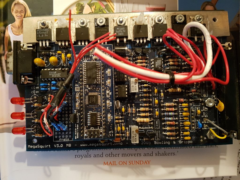
Image
This is the front of the board before desoldering
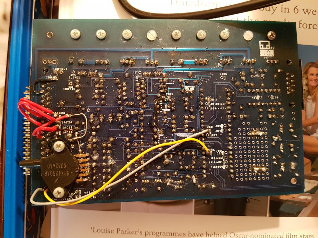
Image
This is the rear of the board before desoldering
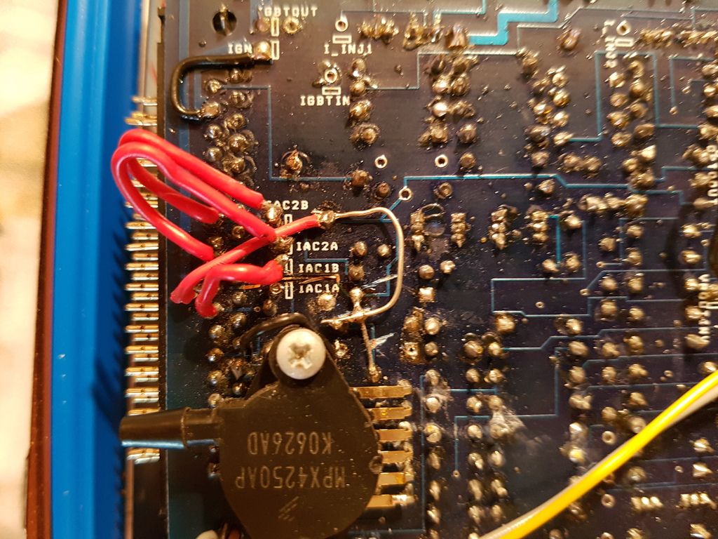
Image
This is a close up of the jumpering around the db37 plug before desoldering, note the jumper that effectively bridges the burnt track from pin 28
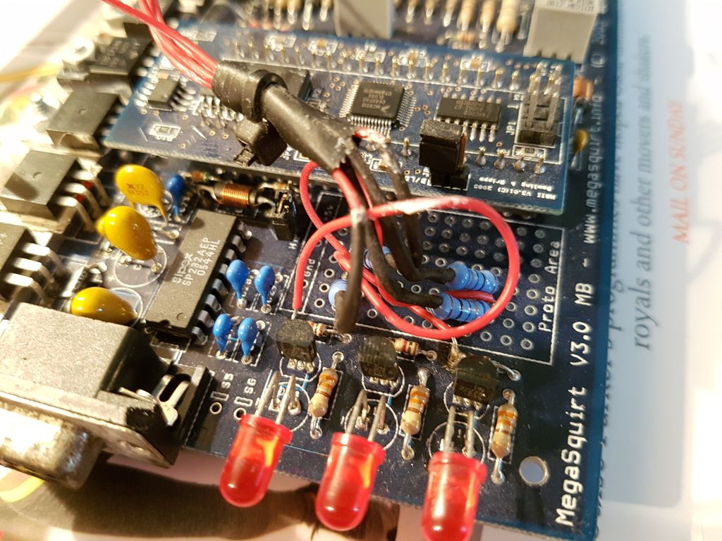
Image
This is some of the ignition circuitry before desoldering, in the proto area
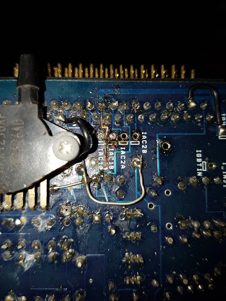
Image
This is the burnt track after desoldering, note I left the uninsulated jumpers in place as they bridged tracks that had previously been cut (god knows why!) I will insulate these jumpers in due course
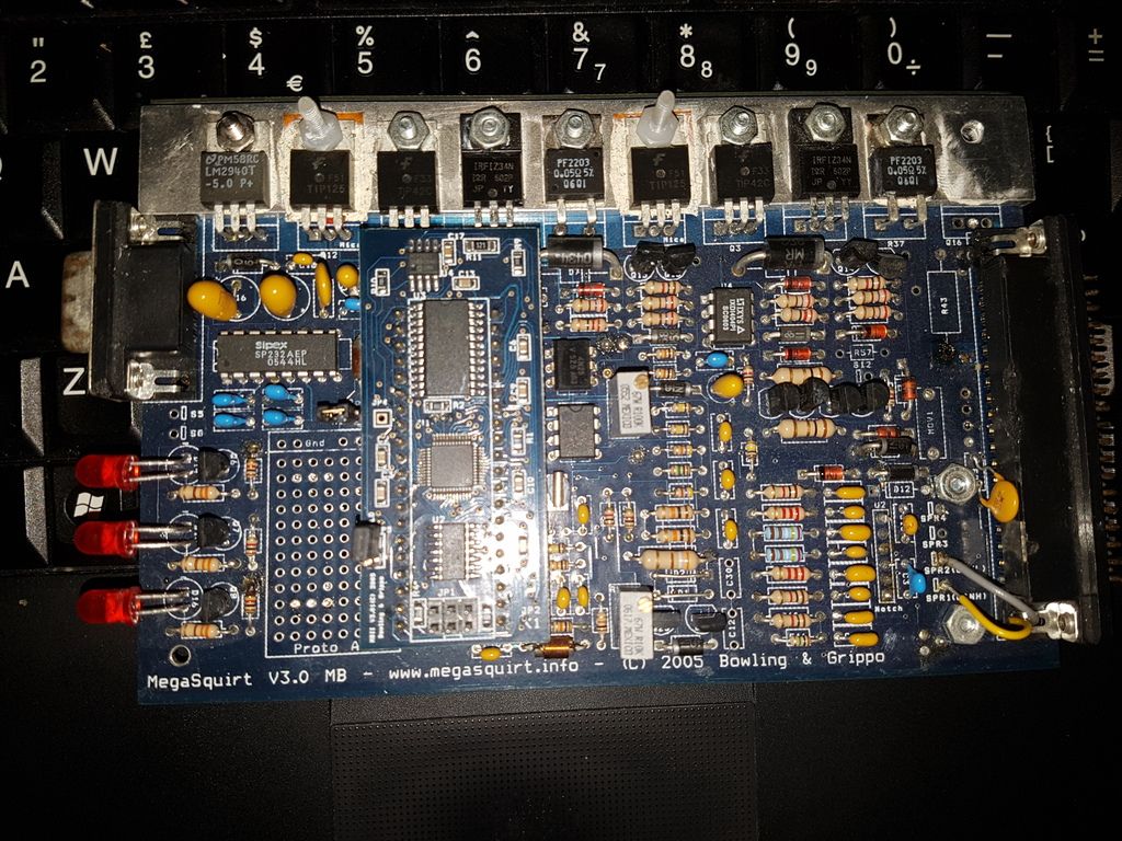
Image
This is the front of the board after desoldering
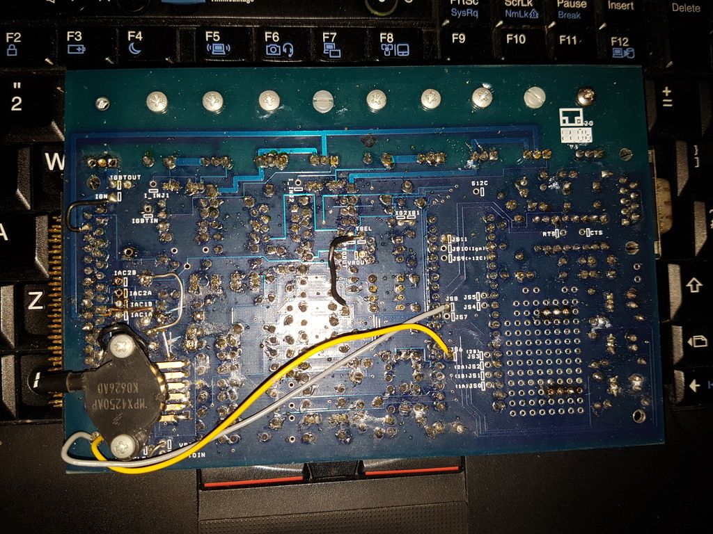
Image
This is the rear of the board after desoldering
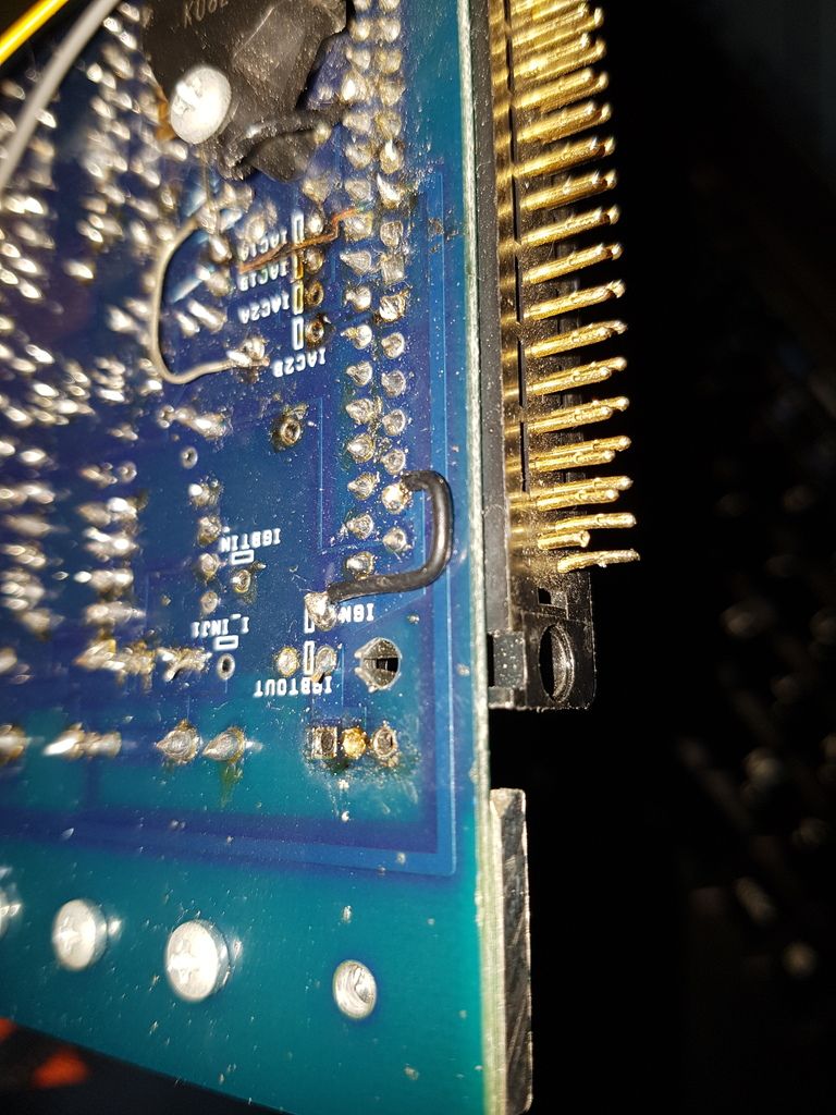
Image
This is another possible issue I found, pin 37 (fuel pump relay?) is broken, so may not be making a connection. Though what I am more confused about it the jumper from the hole marked ign to pin 36, is there a reason for this and should I remove it?
DaveEFI
Super MS/Extra'er
Posts: 4175
Joined: Sun Apr 15, 2012 12:55 am
Location: SW London, UK

Re: New owner of a used MS2 V3.0

Post by DaveEFI »

One tip would be - if using any high current supply like a car battery, do so via a 1 amp fuse. The very last thing you want to do is burn out PCB tracks etc while playing.
But it would make more sense to get a 13.8v power supply than can only manage an amp or so.

It's a temptation when faced with a modified unit to simply remove them all and return to standard. Which is ok if you have decent de-soldering tools and take care. But easy to damage the PCB. So can make sense to make sure you ain't going to need the same mods later.
Rover SD1 3.5 EFI
MS2 V3
EDIS
Tech Edge O2
London UK.
Matt Cramer
Super MS/Extra'er
Posts: 17507
Joined: Thu Apr 16, 2009 8:08 pm

Re: New owner of a used MS2 V3.0

Post by Matt Cramer »

I suspect the IGN to pin 36 jumper is to bypass (yet another) burned trace on the board.
Matt Cramer -1966 Dodge Dart slant six running on MS3X
billr
Super MS/Extra'er
Posts: 6828
Joined: Sun May 15, 2011 11:41 am
Location: Walnut Creek, Calif. USA

Re: New owner of a used MS2 V3.0

Post by billr »

Are you clear on why it wouldn't power-up once you removed the jumper that fixed pin 28? Pin 28 is the primary power input to the board, if that is bad, nothing should work.
DaveEFI
Super MS/Extra'er
Posts: 4175
Joined: Sun Apr 15, 2012 12:55 am
Location: SW London, UK

Re: New owner of a used MS2 V3.0

Post by DaveEFI »

Reading your post again, the first thing to do is get the 5 volt rail working. Remove the processor board and put to one side while fixing this. And replace any other components which are missing on the power supply side.

It's not uncommon for a cap or two to fail short circuit in the power supply side and cause havoc - even burnt tracks.

Print out the schematic for the power supply section, and spend some time studying it. You need to check both 5v and 12v are being distributed to all the various points on the PCB before going further.

With an MS which has been played with by many - like say used for student projects - it could be 12v has been applied to the 5v rail in error. Etc. So just take time and care and check everything. You can repair burnt tracks - but there comes a time when a new or good used PCB might be just easier. Just hope the daughter board is OK.
Rover SD1 3.5 EFI
MS2 V3
EDIS
Tech Edge O2
London UK.
frase29
MS/Extra Newbie
Posts: 5
Joined: Sat Jun 25, 2016 1:04 pm

Re: New owner of a used MS2 V3.0

Post by frase29 »

Thanks very much to all for the advice! I repaired the burnt track, removed the daughterboard and checked all voltages. Happily they all turned out good, the 5v rail had 5v again! and no voltages where they shouldn't have been.

I then put a 1A fuse inline with the car battery i was using, put the daughterboard back in, hooked up my USB-serial cable and success! tunerstudio correctly recognised the megasquirt and read the map again as before. the only sensor connected was the MAP sensor which appeared to be working (by the very unscientific test of blowing on it and seeing if it made the reading a little unstable - it did, and was reading around 100kpa as it should have)

I've also found almost all the missing bits of the megasquirt in various drawers and hiding places, all i'm now missing is D12, what is it used for?

finally, i've hooked up a 12v power supply instead of the battery, still sensibly fused, and ready to begin testing the various circuits, so is there anything i can do without a stim?

thanks again for the tips, all is looking up from my point of view! will probably update the firmware next...
frase29
MS/Extra Newbie
Posts: 5
Joined: Sat Jun 25, 2016 1:04 pm

Re: New owner of a used MS2 V3.0

Post by frase29 »

now successfully updated to the latest firmware, and all still checking out. will start using the i/o tests with a multimeter and see how much i can check with that for outputs! so far i've confirmed all the LEDs work fine...
Post Reply