Hi Guys,
Me and my brother converted a mark 3 ford tansit with an NAT engine (2.0 with ford VV carburettor and LPG singlepoint) to injection with the help of megasquirt, the first step was taken six months ago with building the megasquirt.
Reason we started was that the VV carburettor was very hard to get under control and had quite some fuel consumption, we got our hands on a NAE engine (2.0 scorpio injection?) and transferred the intake manifold and ecu/wiring loom.It sort of worked but it wouldn't idle and had trouble running well.So it could be some sensor or TFI unit or ignition, the camshaft of the NAT engine is also different in profile than the NAE one.So without a good diagnostic system we decided to go the megasquirt way, it was quite an operation but i would recommend it to everyone.There is so much information on the internet its overwhelming, we started building the megasquirt and that gave us a lot of insight in what is where on the board and whats happening.
What also is very nice, is the amount of information.We hooked up the megasquirt for the first time ans same the TPS value dancing, it was not working well, thats why the original setup wasn't working well.
The engine internals are all standard, we use a self drawn lasercut 36-1 setup and standard ford injectors, and it works like a charm, for petrol it is running and idling, VE table made with tunerstudio autotune.all petrol injectors are on bank 2, AFR is very steady.We use a ms2 with ms2extracomms340t2 firmware
On bank 1 are 4 vapour LPG injectors, these are low impedance and we use resistors to use them as high impedance, max power draw is 11 amps.For LPG we still have some problems.The AFR does not keep steady, some things we see/know.
-In test mode the lpg injectors need 4ms before even somthing happens, they have a very long dead-time
-we don't have specs of the injectors, nozzle size unknown
-afr is unstable at all situation
-idle is very low, adjustment by iac is often too late, resulting in a stall
does anyone have suggestions where to look or what to check?
Greets,
Wouter
EDIT:
Added link of car running
https://www.youtube.com/watch?v=_x-azCrcdG8
new user: ford transit 2.0 ohc
Moderators: jsmcortina, muythaibxr
new user: ford transit 2.0 ohc
Last edited by wouter86 on Mon Jul 18, 2016 2:32 pm, edited 1 time in total.
-
Matt Cramer
- Super MS/Extra'er
- Posts: 17507
- Joined: Thu Apr 16, 2009 8:08 pm
Re: new user: ford transit 2.0 ohc
These LPG injectors may need a peak and hold driver - or even some sort of large always-on transistor to drive them.
Matt Cramer -1966 Dodge Dart slant six running on MS3X
Re: new user: ford transit 2.0 ohc
it was on my list but wanted some way to make sure this is the right way to go, since i dont have a way to test without the resistors what the deadtime would be there is no other way than to order one.
So today ordered a peak and hold board, keep you posted how it works out.
Thanks for the reply
So today ordered a peak and hold board, keep you posted how it works out.
Thanks for the reply
Re: new user: ford transit 2.0 ohc
I assembled the peak and hold board today, now i have a wiring question, i checked the forum but could not find my answer.
situation right now:
Bank 1: 4 LPG vapour injectors running simultanous (bad/no idle, long dead-time,unstable AFR)
Bank 2: gasoline injectors simultanous (good idle, power, afr)
Bank 1 and 2 are configured as dual-table, both are constantly working but power is directed with a relay that switches power to petrol or lpg injectors.
I want to investigate if the peak and hold is gonna be the solution, so i need to change 1 variable at the time to determine what the effect is.So now i want to keep everything as it is only bank 1 gets on a peak and hold board with 4 independent transistors and removing the resistor packs.
Wiring question:
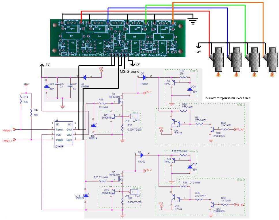
According to this http://www.jbperf.com/p&h_board/v30connect.JPG i need to at least remove D3, D21, C13, C14, D17, D18, R15, R20.By this i remove both outputs to the existing transistors, but i want to keep bank 2 as it is right now, since it is working ok.is it possible to only use output A for the peak and hold? so removing only R15 and D17, and splice that output A into 4 onto the p&h board?
And where are D3, D21, C13, C14 for?can they be kept intact or do i need to remove them when 5v is applied?
The car needs to start on petrol to allow the LPG vapouriser to heat up, so wiring up only the LPG injectors is not gonna work, and 2 p&h boards seems a bit overkill.There might be a good solution around, any suggestions?
situation right now:
Bank 1: 4 LPG vapour injectors running simultanous (bad/no idle, long dead-time,unstable AFR)
Bank 2: gasoline injectors simultanous (good idle, power, afr)
Bank 1 and 2 are configured as dual-table, both are constantly working but power is directed with a relay that switches power to petrol or lpg injectors.
I want to investigate if the peak and hold is gonna be the solution, so i need to change 1 variable at the time to determine what the effect is.So now i want to keep everything as it is only bank 1 gets on a peak and hold board with 4 independent transistors and removing the resistor packs.
Wiring question:
According to this http://www.jbperf.com/p&h_board/v30connect.JPG i need to at least remove D3, D21, C13, C14, D17, D18, R15, R20.By this i remove both outputs to the existing transistors, but i want to keep bank 2 as it is right now, since it is working ok.is it possible to only use output A for the peak and hold? so removing only R15 and D17, and splice that output A into 4 onto the p&h board?
And where are D3, D21, C13, C14 for?can they be kept intact or do i need to remove them when 5v is applied?
The car needs to start on petrol to allow the LPG vapouriser to heat up, so wiring up only the LPG injectors is not gonna work, and 2 p&h boards seems a bit overkill.There might be a good solution around, any suggestions?
-
racingmini_mtl
- Super MS/Extra'er
- Posts: 9130
- Joined: Sun May 02, 2004 6:51 am
- Location: Quebec, Canada
- Contact:
Re: new user: ford transit 2.0 ohc
If you want to keep one bank, you can't use the linked schematic and you can't remove the components. If fact do not use the wiring instructions on the p&h board web page at all. Instead, use this and connect to either INJ1 or INJ2 for your connection point to the p&h board. You don't need to remove any component but simply don't use the injector output on the DB37.
Jean
Jean
Re: new user: ford transit 2.0 ohc
Installed the P&H board and it is now wired as semi-sequential, with a relais that switches between LPG of petrol.
Last week 1 vapour injector was stuck resulting in big backfires, we replaced the injectors with hana 2001 type ones.It is running much better then with the old ones!
Table switching is also implemented and works very well.
Next step in the ' tick-tock' progress is updating the spare megasquirt with a P&H board and tableswitch circuit, and and upgrade it with a second trigger and wasted spark possibility.
For now, we have to drive it like this
https://www.youtube.com/watch?v=8CPN8n0kgwI
Re: new user: ford transit 2.0 ohc
In some situations with driving the car starts to shock , especially at idle and when vacuum starts to to build up (partial-power).
Petrol does not have this problem in any way, so i started logging,The map signal starts jittering and then de rpm and PW follow resulting in a jittering ride.Wide open throttle it drives fine.It has to be somewhere in the lpg system.We fixed the ignition at idle, the ve at idle and the pwm was at open loop mode at 52%.
When listening under the hood the sound of the vapour injectors was erratic.we tried to choke the lpg hose to the injectors and it started to run much smoother, then it leaned out.We imagined the gas pressure was to high for the injectors to cope with, running WOT would reduce de pressure difference making the injectors easier to open.
So we reduced pressure to 1 bar, fixed ignition in idle area, fixed ve in idle area and fixed the pwm in open loop mode.
The result
https://www.youtube.com/watch?v=ziZch5PNqAk
On to the next problem, i built a P&H board on my reserve megasquirt together with table switch and rpm circuits but i did not gat a connection to the PC.
Using a thermal camera (CAT S60) i noticed the polyfuse on the jimstim and ms2 became very hot.I removed the table switch an tacho out circuit but the problem was still there. I removed the voltage regulator (U5?) and after that no more heat build up in the polyfuses.So it seems like a shortage in the 5V circuit.
I put the voltage regulator on a 12V source outside the megasquirt but the output was much lower than 5V, the regulator itself became more than 150+ degrees C so i ordered a few new ones.
With the P&H board installed al the ' old' injector circuits were still intact and maybe used by the stimulator, maybe the problem lies somewhere in there.
To be continued...