I've just converted my 4AGE running MS DIYPNP into COP using SR20 coil packs. However I must've done something wrong or missed something as the car isn't starting now (I'm assuming no spark).
Before conversion:
Single BIP373 firing the factory coil with factory distributor
Mods since conversion:
Soldered in another 3 BIP373s
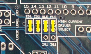
Jumpered the board like this:
Soldered a 100 ohm resistor in the 5 volt position for both R1 and R2
Ran the output of S1-S4 to - on each coil. S1 to cyl 1, S2 to cyl 2 and so on.
Wired the E on each coil to engine ground
Wired the + on each coil straight to the battery (for testing) via a fuse (which hasn't blown)
Just unplugged the spark leads from the distributor
This is all I've done in terms of hardware
On the tune side of things I've mimicked the ignition settings from a guy running the same engine but with Yaris coils which does have a built in igniter unlike these.
I haven't changed anything to accommodate that, could that perhaps be the issue?
I've uploaded my tune before and after these changes as well.
I'd be very grateful if someone could help me out with how to go about troubleshooting this. I've tried using my timing light while cranking on the wires to a coil pack but I'm not sure if it would detect those pulses anyway. I guess one option would be to jam a spark plug lead into a coil pack and run the timing light on that but as of now I'm pretty sure there's no spark at all anyway.
Verify if the spark outputs trigger the coils. Use the output test mode to trigger the outputs. If you can't get your timing light to work, take the spark plug out and ground it on the chassis so you can see the spark.
Also make sure your coils are wired correctly. If you tap the trigger wire on 12V, it will fire.
Rig up a LED for 12v - a 1000 ohm series resistor should be fine - and wire it up to the spark outputs in turn. When cranking the engine it should flash.
Ok, so I've tried firing the coils manually now but didn't manage to get them to fire.
What I did to test is was the following:
Hook up E to engine ground
Hook up + to battery positive terminal
Jam a spark plug into the coil and have it sitting with it's threads grounded on the engine
Tap the - cable on the positive terminal on the battery
Doing this didn't produce any spark from the coil, I also did try to use E as signal and - as ground as well but that didn't work either. I tried this on two different coils without either of them firing.
I also did some measuring on the coils and found the following:
1.2Ω between + and - on all four coils
No continuity between any other terminal combination
No continuity between the spring touching the spark plug top and any of the terminals in the connector (is that an issue?)
Is that as expected? What would be the next thing to try?
One of the two combos I tried did make the coil pack fairly warm though so it was definitely doing something, but I suspect that was just me wiring it up incorrectly.
CRSTune wrote:SR coils typically run a dwell time of 1.9ms.
Verify if the spark outputs trigger the coils. Use the output test mode to trigger the outputs. If you can't get your timing light to work, take the spark plug out and ground it on the chassis so you can see the spark.
Also make sure your coils are wired correctly. If you tap the trigger wire on 12V, it will fire.
I don't know what I was thinking when I posted that. Must've been thinking about testing an external ignitor/internal ignitor COP.
E goes to ground (E stands for Earth in this case).
+ goes to power.
Tap - to ground and you should see it fire.
CRSTune wrote:I don't know what I was thinking when I posted that. Must've been thinking about testing an external ignitor/internal ignitor COP.
E goes to ground (E stands for Earth in this case).
+ goes to power.
Tap - to ground and you should see it fire.
Still no spark with that config. Or, well I get sparks on the negative terminal of the battery when tapping it with -. I also tried swapping - and E and tapping E but then nothing happens at all.
I'm not particulary up on the DIYPNP, but I know the standard uS and uSM need a 1k pull-up to 5v in order to use the ALED and WLED as spark signals. Those transistors are pure ground-switching, with no ability to generate the 5v signal needed to trigger the BIPs (or any other device, for that matter).
Temporarily shut down - back soon!
QuadraMAP Sensor Module -- PWM-to-Stepper Controller -- Dual Coil Driver
Coming soon: OctoMAP Sensor Module TTR Ignition Systems
dontz125 wrote:I'm not particulary up on the DIYPNP, but I know the standard uS and uSM need a 1k pull-up to 5v in order to use the ALED and WLED as spark signals. Those transistors are pure ground-switching, with no ability to generate the 5v signal needed to trigger the BIPs (or any other device, for that matter).
That is correct for a DIYPNP too, but we included pull ups at R1 and R2 for this purpose.
Matt Cramer -1966 Dodge Dart slant six running on MS3X
I've jumpered the board like this as well as soldered a 100 ohm resistor in the 5 volt position for both R1 and R2.
I'm tempted to swap back to single coil just to confirm the MS and plugs are healthy but that still wouldn't explain why I'm unable to fire the coil by tapping the wires on the battery.
Does anyone have similar coils and can re-produce the procedure successfully?
Ok guys, I've made some progress now in my troubleshooting and while using E for ground and - for signal I've managed to get all 4 coils to fire in test mode (great tip by the way. Thanks for that!).
However, it doesn't seem to fire while cranking so I might have to revise my settings.
As mentioned in the first post I've copied the setting over from someone else running COP on a 4age and simply unplugged the lead between the factory coil and the distributor.
Can I test if it's still picking up cam signal and such from the distributor? I'm guessing whatever is supposed to tell it to fire doesn't at the moment?
Here's a file with it cranking. The guy I got the tune from was running a 4AGZE distributor but I think they're the same, not entirely sure though so it's possible I've stuffed up my settings for my setup.
I'm not getting RPM synced after cranking but I can't remember if I'm supposed to without the engine actually firing up or not.
There is no RPM in the log. I only know you're cranking because I see the voltage drop. You need a half or full sync for the ignition coils to start firing.
Your original tune is setup to use basic trigger while the new tune is set to toothed wheel with 24 teeth. That's likely the reason why it doesn't start.
xtimmyx wrote:I tried Basic trigger as well but when I do I blow the fuse (15A) for the coil packs when turning on the ignition.
Power down the coils and injectors totally. Concentrate on getting a sensible RPM reading in a log when cranking first. Everything else relies on that.
Here's a log with me cranking the engine with "Basic trigger". I get an RPM reading but from my understanding I can't run sequential ignition with basic trigger?
So I'm guessing the issue now is how to get the MS to read the signal from the factory distributor in "Dual wheel" mode? For some reason the settings I found from the GZE engine doesn't seem to work with my GE then?
Thanks again everyone. It's thanks to forums like this I've even made it this far.
The original distributor has only a 4 tooth trigger. There is a tooth for every cylinder but there is no way for the ECU to identify TDC or phase. That's why it only works for batch fire fuel and distributors. The other calibration is setup to use the later 24/1 distributors. These are higher accuracy and could actually benefit your setup (you'll see less timing drift).
I haven't done this so someone correct me if I'm wrong. To run sequential with the 4/1 distributor, you'll need to use the cam input signal and setup the configuration for toothed wheel running 4 teeth at cam speed and a 1 tooth cam.
Thanks I believe you're absolutely right. Looking at the workshop manual the GZE (and possibly the smallport too have the 24 tooth dizzy). I'll try and source one of those instead. The current one is 4 wire as well so hopefully wiring shouldn't be too bad.
I found a 20v engine pin-out which uses NE wired to VR+, G1 wired to VR2 and NE-/G- wired ti VR- so I'm guessing that' what I'd like to do as well.
4age_20v_diypnp wiring.png
As it seems neither VR+, VR- or VR2 is currently used in my adapter board am I perhaps best of just running the wiring from the new dizzy separately and to the D15 rather than trying tap into the existing harness?
4age_ecu.png
I've made a little graph of what I think it could be. Does that seem to make sense?