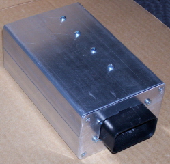
I have done some testing in a worst case setup with the 4-driver box. I used four 2 Ohm resistors instead of injectors. This puts the driver in current limiting (hold) mode almost instantly since the peak is reached very fast due to a very low inductance. This generates the most heat from the TIP122.
It appears that the small case is too small to effectively dissipate the heat generated. I did some tests at about 85-90% duty cycle and the case became too hot to handle comfortably after a few minutes. I then put the box on an empty relay board case and this made the situation better. It still wasn't enough but the contact was not optimum.
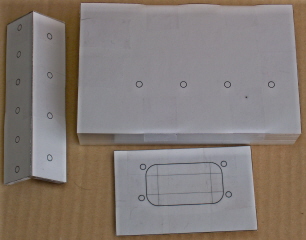
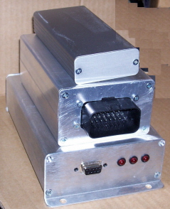
What I will do is get a 1/8" thick U-shaped aluminium bar and bolt it to the case using the transistor screws and heatsink grease. I think this will solve the issue. By the way, real world setups will be much less troublesome than my test setup. With a real setup, the peak period will be a significant percentage of the duty cycle and the peak mode generates much less heat in the transistors due to how they work. Also, most injectors have more impedance than the 2 Ohms I've used which will make quite a difference. Finally, most engines will not operate for extended periods at high duty cycles. I'll report back as soon as I have made the tests with the additional heatsink.
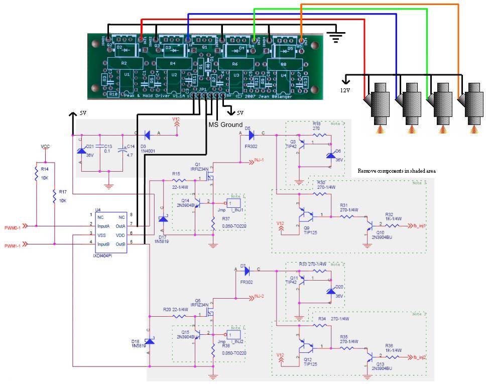
Since the v2.0 is not an option for more than 4 drivers, I have done another design which solves the packaging issue and should also solve the heat issue. Here is a picture of the planned board (click for a larger picture):
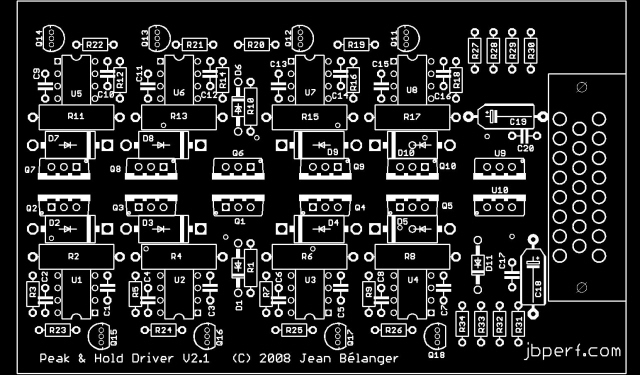
The transistors will bolt to a 1/8" think T-shaped aluminium bar which will also bolt to the case. The board will be 3"x5" and will fit in the same case as the relay board (with both halves, of course) with the board in one half and the heatsink bolted to the other half. There is an on-board Ampseal connector with 23 contacts: 8 for the injectors, 8 for the injector control (to the ECU), 1 for 12V, 1 for low-current ground, and 5 for high current grounds. The larger mass of the case together with the large heatsink should be sufficient but there is always the possibility of using an external heatsink.
I'm getting parts to check the design and layout and I'll have the board made when I have checked everything fits as it should. The BOM will be the same as the 2-board v2.0 except for the case and the connector. Since the Ampseal connector can be a bit expensive it will be possible to do as for the v2.0 and use wire soldered directly to the board and external connectors.
I plan to have both the v2.0 and v2.1 available since they both have their application (assuming I can solve the heat issue). I may also provide heatsinks cut and drilled as needed but I'll have to see about that one.
Jean