Speaking of being within a degree or two of the target...
I've found that Hold Duty for the miata is inconsistent. I guess there's something about oil temp or pressure or mechanical slop that prevents a consistent hold duty. If I test it under no load, I get, say, 53%. But in practice, 53 is too low... so when I'm at speed (moderate load, higher RPM) the hold duty appears to be more like 55-56.
I can tell it's wrong because as I approach the target within 2 degrees, duty drops to 53 and then the angle drops away from the target. duty increases to compensate and the cycle repeats.
I turned off hold duty and the angle holds closer to the target without oscillating (no chnages to PID).
My other issue is at full retard. The angle varies from 0-2 degrees and if target is lower than where the cam angle rests, it drives the duty cycle to zero to try to match the target. When it has a high target, it can sometimes lag while duty cycle catches back up. I've tried setting the target to 1.5 degrees but it still doesn't work exactly how I want it to.
VVT ideas and testers
Moderators: jsmcortina, muythaibxr
-
jsmcortina
- Site Admin
- Posts: 39617
- Joined: Mon May 03, 2004 1:34 am
- Location: Birmingham, UK
- Contact:
Re: VVT ideas and testers
As it happens, I added an option last night to allow the measured angle to go below zero or the range checking can be disabled completely. I believe these ought to help.y8s wrote:My other issue is at full retard. The angle varies from 0-2 degrees and if target is lower than where the cam angle rests, it drives the duty cycle to zero to try to match the target. When it has a high target, it can sometimes lag while duty cycle catches back up. I've tried setting the target to 1.5 degrees but it still doesn't work exactly how I want it to.
James
I can repair or upgrade Megasquirts in UK. http://www.jamesmurrayengineering.co.uk
My Success story: http://www.msextra.com/forums/viewtopic ... 04&t=34277
MSEXTRA documentation at: http://www.msextra.com/doc/index.html
New users, please read the "Forum Help Page".
My Success story: http://www.msextra.com/forums/viewtopic ... 04&t=34277
MSEXTRA documentation at: http://www.msextra.com/doc/index.html
New users, please read the "Forum Help Page".
-
AbatelliCristian
- Super MS/Extra'er
- Posts: 855
- Joined: Sun Oct 10, 2010 6:33 am
Re: VVT ideas and testers
Tomorrow I try and record log....
-
jsmcortina
- Site Admin
- Posts: 39617
- Joined: Mon May 03, 2004 1:34 am
- Location: Birmingham, UK
- Contact:
Re: VVT ideas and testers
I'll send you a test code later with these two new options too.AbatelliCristian wrote:Tomorrow I try and record log....
James
I can repair or upgrade Megasquirts in UK. http://www.jamesmurrayengineering.co.uk
My Success story: http://www.msextra.com/forums/viewtopic ... 04&t=34277
MSEXTRA documentation at: http://www.msextra.com/doc/index.html
New users, please read the "Forum Help Page".
My Success story: http://www.msextra.com/forums/viewtopic ... 04&t=34277
MSEXTRA documentation at: http://www.msextra.com/doc/index.html
New users, please read the "Forum Help Page".
-
AbatelliCristian
- Super MS/Extra'er
- Posts: 855
- Joined: Sun Oct 10, 2010 6:33 am
Re: VVT ideas and testers
Thanks... I try and post the result...
The next week I'm out of my town. I return 28
The next week I'm out of my town. I return 28
-
skidude108
- MS/Extra Newbie
- Posts: 11
- Joined: Fri Sep 19, 2008 2:52 pm
Re: VVT ideas and testers
I'm trying to get VVT working on my miata, and it appears the y8s flyback diode is giving me issues. I've got VVT on Nitrous 1 output, and a 1N4005 diode between there and 12V (stripe to 12). Without that diode, I can test VVT duty cycle up to about 75%, after which the tach goes nuts and the engine revs, and I can't get the cam to retard again.
With the diode in place, I get a lot of issues with sensor readings becoming erratic when duty gets up to around 60%, and then the MS resets and goes back to the previously burned value.
With the diode in place, I get a lot of issues with sensor readings becoming erratic when duty gets up to around 60%, and then the MS resets and goes back to the previously burned value.
2002 Miata, MS3 + MS3X.
Re: VVT ideas and testers
I'm just looking for a little clarification on the VVT feature.
I'm looking to install this on my 2gr-fe powered Toyota MR2 that has quad VVT-i. the problem is i can't figure out if this code is compatible with my cam pattern or if code would need to be changed.
my plan if it is compatible is to let the stock ECU control the VVT-i during the initial tuning and just steal it's base values before giving megasquirt control of the solenoids.
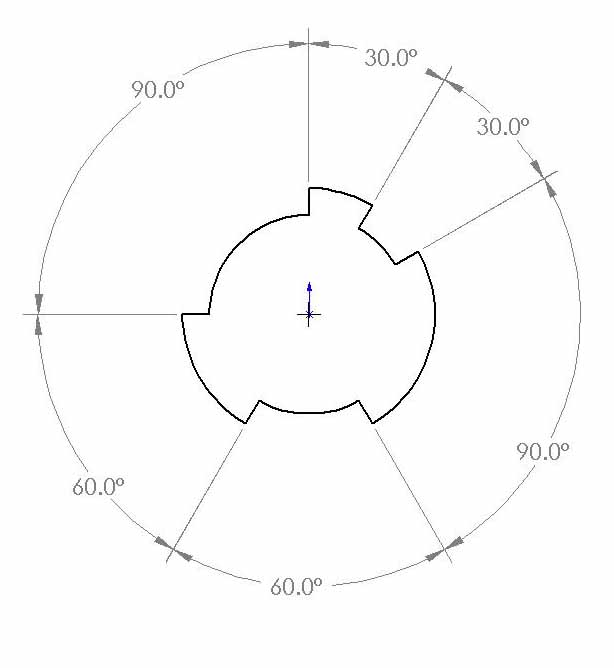
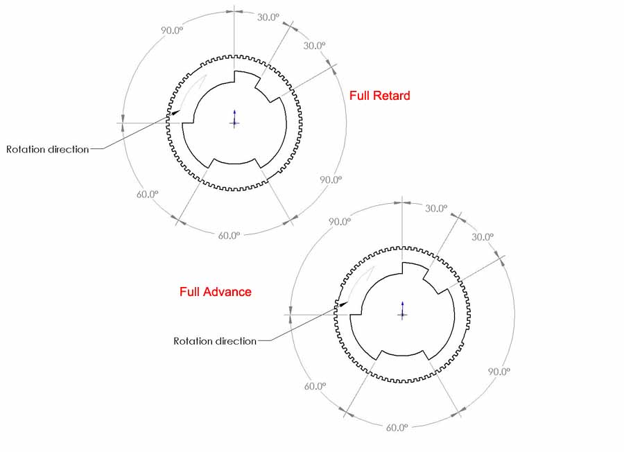
the trigger pattern is visible here: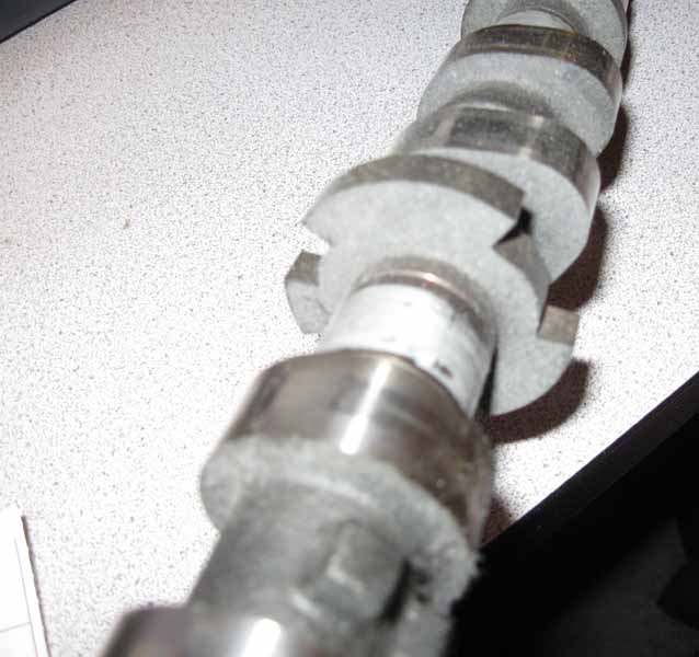 there are three teeth of three sizes, here's a drawing of their organization:
I have no idea where TDC is on that since i'm doing this on a spare cam i have sitting here. but i suspect this should be easy to figure out by looking at the cam/crank scope view once i hook it up to megasquirt.
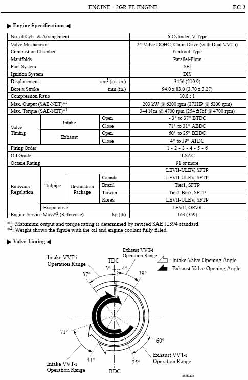
and as you can in the image below, the intake can move by 40degrees and the exhaust can move 35degrees
for what it's worth, i do have experience with megasquirt. i used it to power a WWII radial airplane engine and i had to design all the triggers/pickups. and i design embedded software for a living so i understand the inner workings fairly well.
Thanks everyone!
I'm looking to install this on my 2gr-fe powered Toyota MR2 that has quad VVT-i. the problem is i can't figure out if this code is compatible with my cam pattern or if code would need to be changed.
my plan if it is compatible is to let the stock ECU control the VVT-i during the initial tuning and just steal it's base values before giving megasquirt control of the solenoids.
the trigger pattern is visible here:
there are three teeth of three sizes, here's a drawing of their organization:I have no idea where TDC is on that since i'm doing this on a spare cam i have sitting here. but i suspect this should be easy to figure out by looking at the cam/crank scope view once i hook it up to megasquirt.
and as you can in the image below, the intake can move by 40degrees and the exhaust can move 35degrees
for what it's worth, i do have experience with megasquirt. i used it to power a WWII radial airplane engine and i had to design all the triggers/pickups. and i design embedded software for a living so i understand the inner workings fairly well.
Thanks everyone!
-
AbatelliCristian
- Super MS/Extra'er
- Posts: 855
- Joined: Sun Oct 10, 2010 6:33 am
Re: VVT ideas and testers
Hi, James, I have tried your code. Is all ok, but there is a bug on cam4 read angle. The sensor input not read. The output is ok and the timing table intake is ok (vvt2 work).
I have tried input "falling" and rising" on cam4 but not work
I have tried input "falling" and rising" on cam4 but not work
-
AbatelliCristian
- Super MS/Extra'er
- Posts: 855
- Joined: Sun Oct 10, 2010 6:33 am
Re: VVT ideas and testers
You setting "0" on min and max for test duty....I'm trying to get VVT working on my miata, and it appears the y8s flyback diode is giving me issues. I've got VVT on Nitrous 1 output, and a 1N4005 diode between there and 12V (stripe to 12). Without that diode, I can test VVT duty cycle up to about 75%, after which the tach goes nuts and the engine revs, and I can't get the cam to retard again.
With the diode in place, I get a lot of issues with sensor readings becoming erratic when duty gets up to around 60%, and then the MS resets and goes back to the previously burned value.
-
skidude108
- MS/Extra Newbie
- Posts: 11
- Joined: Fri Sep 19, 2008 2:52 pm
Re: VVT ideas and testers
I don't know why, but when I moved the diode from the expansion board to the wiring harness, the problem fixed itself.AbatelliCristian wrote:You setting "0" on min and max for test duty....
2002 Miata, MS3 + MS3X.
-
jsmcortina
- Site Admin
- Posts: 39617
- Joined: Mon May 03, 2004 1:34 am
- Location: Birmingham, UK
- Contact:
Re: VVT ideas and testers
I know why, which is why I posted improved instructions.
The original method that y8s posted of using a diode on the MS3X board itself is feeding the flyback energy into the Megasquirt mainboard power supply circuit instead of recirculating it throught the VVT solenoid. Connecting to S12 (or 12V in the loom) correctly recirculates it through the solenoid.
James
I can repair or upgrade Megasquirts in UK. http://www.jamesmurrayengineering.co.uk
My Success story: http://www.msextra.com/forums/viewtopic ... 04&t=34277
MSEXTRA documentation at: http://www.msextra.com/doc/index.html
New users, please read the "Forum Help Page".
My Success story: http://www.msextra.com/forums/viewtopic ... 04&t=34277
MSEXTRA documentation at: http://www.msextra.com/doc/index.html
New users, please read the "Forum Help Page".
Re: VVT ideas and testers
y8s is lazy and doesn't want to monkey with his factory harness.
but I might do it anyway at some point.
but I might do it anyway at some point.
-
jsmcortina
- Site Admin
- Posts: 39617
- Joined: Mon May 03, 2004 1:34 am
- Location: Birmingham, UK
- Contact:
Re: VVT ideas and testers
I wouldn't have classed you as lazy, seems you've been spending time to provide a lot of valuable feedback.y8s wrote:y8s is lazy and doesn't want to monkey with his factory harness.
Move that diode banded end to "S12" on the Megasquirt mainboard and it should be a lot better.
James
I can repair or upgrade Megasquirts in UK. http://www.jamesmurrayengineering.co.uk
My Success story: http://www.msextra.com/forums/viewtopic ... 04&t=34277
MSEXTRA documentation at: http://www.msextra.com/doc/index.html
New users, please read the "Forum Help Page".
My Success story: http://www.msextra.com/forums/viewtopic ... 04&t=34277
MSEXTRA documentation at: http://www.msextra.com/doc/index.html
New users, please read the "Forum Help Page".
-
jsmcortina
- Site Admin
- Posts: 39617
- Joined: Mon May 03, 2004 1:34 am
- Location: Birmingham, UK
- Contact:
Re: VVT ideas and testers
I'll try this out later. Developing and testing the 4 channel VVT is rather tricky as I don't have an easy means to generate the signals.AbatelliCristian wrote:Hi, James, I have tried your code. Is all ok, but there is a bug on cam4 read angle. The sensor input not read.
James
I can repair or upgrade Megasquirts in UK. http://www.jamesmurrayengineering.co.uk
My Success story: http://www.msextra.com/forums/viewtopic ... 04&t=34277
MSEXTRA documentation at: http://www.msextra.com/doc/index.html
New users, please read the "Forum Help Page".
My Success story: http://www.msextra.com/forums/viewtopic ... 04&t=34277
MSEXTRA documentation at: http://www.msextra.com/doc/index.html
New users, please read the "Forum Help Page".
-
jsmcortina
- Site Admin
- Posts: 39617
- Joined: Mon May 03, 2004 1:34 am
- Location: Birmingham, UK
- Contact:
Re: VVT ideas and testers
I'm pretty sure that would need a custom decoder.Marc wrote:I'm looking to install this on my 2gr-fe powered Toyota MR2 that has quad VVT-i. the problem is i can't figure out if this code is compatible with my cam pattern or if code would need to be changed.
However, if you can hook up an MS3, enable spark mode "log crank and cam", key off/on and then take a composite log during cranking that might shed some more light on it.
James
I can repair or upgrade Megasquirts in UK. http://www.jamesmurrayengineering.co.uk
My Success story: http://www.msextra.com/forums/viewtopic ... 04&t=34277
MSEXTRA documentation at: http://www.msextra.com/doc/index.html
New users, please read the "Forum Help Page".
My Success story: http://www.msextra.com/forums/viewtopic ... 04&t=34277
MSEXTRA documentation at: http://www.msextra.com/doc/index.html
New users, please read the "Forum Help Page".
Re: VVT ideas and testers
i can certainly do that and i'd love to be able to help you guys get Toyota VVT-i support in here.
i can pull the MS3 ecu from my other car out temporairly and connect it to my 2gr so i can get a log trace. I don't really want to purchase another MS3 ecu until i have a decent feeling that we can get the VVT-i working. this motor pretty much runs like hell without it.
unless of course you feel pretty confident that we can get this going. if so, i'll go ahead and get started on the wiring for the car. what's your confidence level?
-
jsmcortina
- Site Admin
- Posts: 39617
- Joined: Mon May 03, 2004 1:34 am
- Location: Birmingham, UK
- Contact:
Re: VVT ideas and testers
Use the other ECU to capture the crank and cam signals, then I can make a judgement. Thinking some more, that cam pattern is "ok" for VVT position as one edge is evenly spaced every 120 degrees. How the pattern ties in with the crank is another matter though.
James
James
I can repair or upgrade Megasquirts in UK. http://www.jamesmurrayengineering.co.uk
My Success story: http://www.msextra.com/forums/viewtopic ... 04&t=34277
MSEXTRA documentation at: http://www.msextra.com/doc/index.html
New users, please read the "Forum Help Page".
My Success story: http://www.msextra.com/forums/viewtopic ... 04&t=34277
MSEXTRA documentation at: http://www.msextra.com/doc/index.html
New users, please read the "Forum Help Page".
Re: VVT ideas and testers
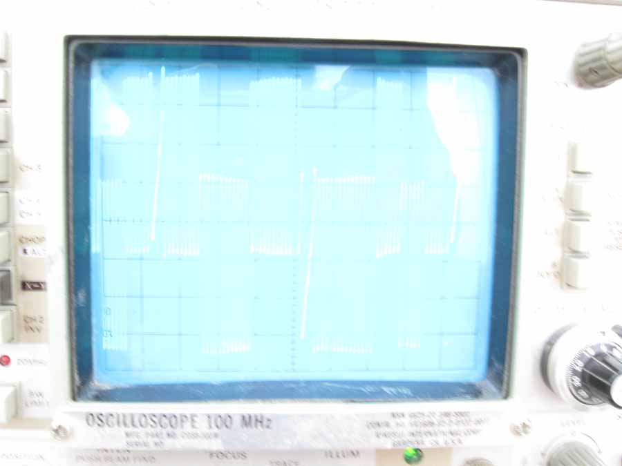
well, i went in the shop to work on it and noticed that i did not have any spare DB36 connectors to be able to hook up the ECU in piggy back but i still wanted an answer so i dug out my older than dirt o'scope and did some investigation.
the phosphorous layer on this scope isn't tuned to such slow signals so i had to use the camera's slow shutter speed to capture the entire signal. i also had to add the signals together to make it so they were both visible on the same picture because of the way the scope works.
but anyways, it gave me this barely viewable answer:
and after some careful analysis (the cam signal is inverted) i was able to figure out that this is the overlapped wheel pattern:
also, while i was there i measured the pwm frequency and it looked like the following:
pwm frequency: 300Hz
Minimum pwm = 20%
Maximum pwm = 80%
-
jsmcortina
- Site Admin
- Posts: 39617
- Joined: Mon May 03, 2004 1:34 am
- Location: Birmingham, UK
- Contact:
Re: VVT ideas and testers
That should work now using "Dual wheel with missing tooth" and "Poll level" then set 3 teeth on the cam and choose the edge to give stable VVT reported angle.
On the poll level, notice how on "tooth#1" on the crank (the first tooth after the missing region) that on one phase the cam is always high and on the other phase it is always low ? That gives simple phase detection. Also notice that one edge on the cam signal is evenly spaced every 120deg - that's the one to use.
James
I can repair or upgrade Megasquirts in UK. http://www.jamesmurrayengineering.co.uk
My Success story: http://www.msextra.com/forums/viewtopic ... 04&t=34277
MSEXTRA documentation at: http://www.msextra.com/doc/index.html
New users, please read the "Forum Help Page".
My Success story: http://www.msextra.com/forums/viewtopic ... 04&t=34277
MSEXTRA documentation at: http://www.msextra.com/doc/index.html
New users, please read the "Forum Help Page".
Re: VVT ideas and testers
yeah, i noticed that as i was drawing the diagrams. i figured that's what you were looking for.
so if i have it right, here's what i need then:
crank trigger: 36-2
crank sensor: VR
720 sync based on poll level of CAM 1 on tooth 1 of crank
cam triggers: 3 tooth detect on rising edge of pulse (unless MS3 hardware reverses it)
cam sensors: hall effect
frequency:306Hz
then it's just a question of playing with the PID settings until it can maintain cam control properly.
looks like i'm ordering another MS3 controller then thanks for your help, i'll keep you guys posted with the results
so if i have it right, here's what i need then:
crank trigger: 36-2
crank sensor: VR
720 sync based on poll level of CAM 1 on tooth 1 of crank
cam triggers: 3 tooth detect on rising edge of pulse (unless MS3 hardware reverses it)
cam sensors: hall effect
frequency:306Hz
then it's just a question of playing with the PID settings until it can maintain cam control properly.
looks like i'm ordering another MS3 controller then