I know in the manual it recommends running several items off a single fuel pump relay for safety's sake. I.E coils, fuel pump, injectors, and O2 sensor (for sensor life). But is it also safe to run multiple relays off the single fuel pump enable trigger wire? I ask because I am going to run a good sized fuel pump (Weldon DB2025-A) and 8 IGN-1A coils so both setups require a pretty good amount of current. I guess I could run one really large fuel pump relay, but I am also thinking about running 3 smaller relays. 1 for the coils, 1 for the fuel pump, and then 1 for the injectors and O2 sensor and splitting the fuel pump enable trigger to each.
Does that make sense? What are you guys doing?
Relay Strategy
Moderators: jsmcortina, muythaibxr
Relay Strategy
1995 Ford Lightning. Dart based 427 Windsor, Novi 2000, full sequential, E-85, etc. MS3X/v3.57
http://www.buildpics.org/
http://www.buildpics.org/
-
billr
- Super MS/Extra'er
- Posts: 6828
- Joined: Sun May 15, 2011 11:41 am
- Location: Walnut Creek, Calif. USA
Re: Relay Strategy
It all depends on the current draw of the relays. You can connect as many as you want to the FP output, as long as their combined draw doesn't exceed the limit for that output. The same applies to a single "really large" relay, if it has a "really large" coil that draws too much current, then that will gain you nothing. Relays are available in a wide range of combinations of coil power, rated voltage, rated current, pull-in/drop-out voltage, cycle life, size, cost, etc. You need to pore through the specs and settle on the parameters that are most important to you.
You could, of course, put a relay between the FP output and all the rest of them...
You could, of course, put a relay between the FP output and all the rest of them...
Re: Relay Strategy
Right, exactly. Isn't the fuel pump enable a ground switch? So there's nothing to exceed right?
Sent from my iPhone using Tapatalk
Sent from my iPhone using Tapatalk
1995 Ford Lightning. Dart based 427 Windsor, Novi 2000, full sequential, E-85, etc. MS3X/v3.57
http://www.buildpics.org/
http://www.buildpics.org/
-
slow_hemi6
- Super MS/Extra'er
- Posts: 4122
- Joined: Fri May 07, 2004 3:33 am
- Location: Australia
Re: Relay Strategy
Current is a constant through all parts of a series circuit. Of course the driver carries current and it has a limit.
Find the Manuals up top under Quick links: Manuals. 
Cheers Luke
Cheers Luke
Re: Relay Strategy
That is one way to do it.billr wrote: You could, of course, put a relay between the FP output and all the rest of them...
This way you need an extra relay, but each one has its own single job, easy on fault finding.
Can be the same type which is used in OEM istalls to drive, lights, ignition coils, fuel pump.
Second way, just drive one of the relays from the FP output.
And use the output contact of this relay to connect to the coils of the other ones.
This way you have one relay whit two functions, more difficult on fault finding.
On this one I would use the fuel pump relay, but thats my mind trying to be logical
And check if the MS output is up to it to drive the needed current.
Re: Relay Strategy
.Raymond_B wrote:I know in the manual it recommends running several items off a single fuel pump relay for safety's sake. I.E coils, fuel pump, injectors, and O2 sensor (for sensor life). But is it also safe to run multiple relays off the single fuel pump enable trigger wire? I ask because I am going to run a good sized fuel pump (Weldon DB2025-A) and 8 IGN-1A coils so both setups require a pretty good amount of current. I guess I could run one really large fuel pump relay, but I am also thinking about running 3 smaller relays. 1 for the coils, 1 for the fuel pump, and then 1 for the injectors and O2 sensor and splitting the fuel pump enable trigger to each.
Does that make sense? What are you guys doing?
You could feed your extra relay coils from the pump high current circuit. And avoid any extra load to the MS pump driver. Use a series diode to feed each one of those extra relay coils to prevent any possibility of interaction between them.
The MS pump driver circuit is nominally 1 amp peak load.
Rover SD1 3.5 EFI
MS2 V3
EDIS
Tech Edge O2
London UK.
MS2 V3
EDIS
Tech Edge O2
London UK.
Re: Relay Strategy
Looking around for a diagram to understand this all better I found this. Seems pretty straightforward?
http://www.msextra.com/forums/viewtopic ... 31&t=55597
Sent from my iPhone using Tapatalk
http://www.msextra.com/forums/viewtopic ... 31&t=55597
Sent from my iPhone using Tapatalk
1995 Ford Lightning. Dart based 427 Windsor, Novi 2000, full sequential, E-85, etc. MS3X/v3.57
http://www.buildpics.org/
http://www.buildpics.org/
Re: Relay Strategy
This is the/my second way.Raymond_B wrote:Looking around for a diagram to understand this all better I found this. Seems pretty straightforward?
http://www.msextra.com/forums/viewtopic ... 31&t=55597
Sent from my iPhone using Tapatalk
remark: Put a fuse for each load in the battery line !!
Re: Relay Strategy
Yes, absolutely! Thank you.
Sent from my iPhone using Tapatalk
Sent from my iPhone using Tapatalk
1995 Ford Lightning. Dart based 427 Windsor, Novi 2000, full sequential, E-85, etc. MS3X/v3.57
http://www.buildpics.org/
http://www.buildpics.org/
Re: Relay Strategy
OK, sat down with DipTrace and worked this out. This isolates the MS to it's own relay and a single accessory relay that triggers all other relays.
Any mistakes or misunderstandings?

Any mistakes or misunderstandings?
1995 Ford Lightning. Dart based 427 Windsor, Novi 2000, full sequential, E-85, etc. MS3X/v3.57
http://www.buildpics.org/
http://www.buildpics.org/
Re: Relay Strategy
Also thinking about running the fuel pump trigger from the Megasquirt through the Ford fuel pump inertia switch. That way in an impact the fuel pump, coils, O2, and injectors would shutdown.
1995 Ford Lightning. Dart based 427 Windsor, Novi 2000, full sequential, E-85, etc. MS3X/v3.57
http://www.buildpics.org/
http://www.buildpics.org/
Re: Relay Strategy
That seems almost alright to me, inertia switch is also good option.
Remark on the fuses, put them between +12V and the relay contact.
This way relay contacts are also protected and there is less unfused wire (between battery and fuse).
And it is easier on checking fuses, your relais don't need to be activated to check them.
Remember, first function of a fuse is to protect wire and avoiding fire, you dont want that in any car or motorcycle.
Re: Relay Strategy
Sounds logical, I was just copying the manual and it had the fuses post relays, but pre does make sense.LAV1000 wrote:That seems almost alright to me, inertia switch is also good option.
Remark on the fuses, put them between +12V and the relay contact.
This way relay contacts are also protected and there is less unfused wire (between battery and fuse).
And it is easier on checking fuses, your relais don't need to be activated to check them.
Remember, first function of a fuse is to protect wire and avoiding fire, you dont want that in any car or motorcycle.
1995 Ford Lightning. Dart based 427 Windsor, Novi 2000, full sequential, E-85, etc. MS3X/v3.57
http://www.buildpics.org/
http://www.buildpics.org/
Re: Relay Strategy
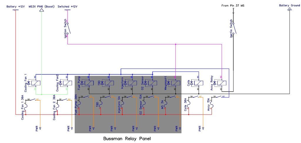
What better way to spend your lunch hour than cleaning up your relay layout  Originally I had wanted to run everything through the Bussman panel, but it can only be wired for all pos or all neg switched relays. Also the smallish connectors did not support a 40A relay which I will be using for my IGN-1A coils. So the coils and neg switched "Accessory" relay are separate. In addition I had two big Tyco relays that came with the e-fans I purchsed so I will use those as well.
1995 Ford Lightning. Dart based 427 Windsor, Novi 2000, full sequential, E-85, etc. MS3X/v3.57
http://www.buildpics.org/
http://www.buildpics.org/
Re: Relay Strategy
Can pin 6 handle 2 relays ?
Re: Relay Strategy
Darn good question, that's my "electrical newbness" showing again. Because it's ground switched I just tied them together, I'll double check. Thank you for the sharp eye!LAV1000 wrote:Can pin 6 handle 2 relays ?
On edit: Looking at the manual pin 6 on MS3X is 3 amp.
1995 Ford Lightning. Dart based 427 Windsor, Novi 2000, full sequential, E-85, etc. MS3X/v3.57
http://www.buildpics.org/
http://www.buildpics.org/
Re: Relay Strategy
Probably going to mess this up, but if I use the formula of P=I/V and flip it around to I=P/V
Then I=3.9watts (the rated coil power of the relay I am using)/12VDC = 0.325A Does this make sense or have I horribly failed at maths and or electronics?
Then I=3.9watts (the rated coil power of the relay I am using)/12VDC = 0.325A Does this make sense or have I horribly failed at maths and or electronics?
1995 Ford Lightning. Dart based 427 Windsor, Novi 2000, full sequential, E-85, etc. MS3X/v3.57
http://www.buildpics.org/
http://www.buildpics.org/
Re: Relay Strategy
those 3 Amps should be enough to drive the two relays.
And; P(Watt)= I(Amps) x U(Volts) >>> I=P/U
In a Ideal world this would work but coils of relays act a bit different and have a Inrush current.
But its no problem on this set up
And; P(Watt)= I(Amps) x U(Volts) >>> I=P/U
In a Ideal world this would work but coils of relays act a bit different and have a Inrush current.
But its no problem on this set up
Re: Relay Strategy
Much appreciated, thank you!LAV1000 wrote:those 3 Amps should be enough to drive the two relays.
And; P(Watt)= I(Amps) x U(Volts) >>> I=P/U
In a Ideal world this would work but coils of relays act a bit different and have a Inrush current.
But its no problem on this set up
1995 Ford Lightning. Dart based 427 Windsor, Novi 2000, full sequential, E-85, etc. MS3X/v3.57
http://www.buildpics.org/
http://www.buildpics.org/