billr wrote:Put the MS3X board and its stim aside for now, remove it as a possible problem/confusion until you have the basic "tachin" (rpm display) under control.
Pictures I can look at (or help in using the ones already posted) is the only way I can check over the board build. Probing with a meter may get tedious/frustrating if there is something wrong or incomplete with the assembly.
Can you check Q22 & Q23 are orientated correctly and not shorting above and below. (Magnifying glass required) . Also make sure that U4 & U7 are in the correct places. I can't read them from the photo.
Ok i have almost went blind trying to see those legs on Q22 and Q23 . I feel like Q22 had a possible solder bridge and cleaned it up. Put everything back together and still no signal.
I also saw a test on DIYautotune where I put U1 pins 21 and 22 to ground and the inj leds lit up on the mainboard. Mine did come on . Hope that's a good sign.
If I think of any more things to check I'll let you know.
You did check those 2 chips U7 & U4 didn't you?
Also I noticed you haven't linked out R43, seeing as you've got the board apart you might as well sort that.
I adjusted R11 to 2.5v and I also adjusted R56 to 2.5v. Still no signal. I sent a message to Peter Florance @ PF Tuning. Maybe I can send it to him and get this straightened out. Just waiting to hear back from him.
I'm sure you'll get it sorted. You never know it might just be a duff transistor, you know, those ones that nearly made you blind checking for shorts.
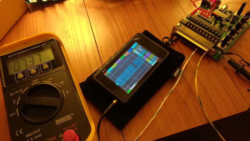
As a little extra info here's a pic of what you should expect out of your Jimstim for the vr output. I borrowed a mini oscilloscope off a friend to check it out. I also attached a standard multimeter just in case you didn't have an oscilloscope.
Can someone recommend a place that repairs Megasquirt. I haven't been able to get in touch with PF Tuning. I am sure he's busy is why.
Or is it possible to buy the Mainboard only that is complete or close to it. Just trying to see what options I have.
What is you schedule like now, and your frustration level? The pictures of your assembled mainboard don't show anything ugly, dumping it seems like quite a waste. I think we can work this out, but it make take a while. As you can tell, I don't always have time to study things and suggest more tests right away. And, there are three threads going right now with similar problems regarding board trouble-shooting. I tend to give priority to the easy-to-answer questions first, kind of a "triage" approach.
As an option, I am willing to work with your board "hands on" if you ship it to me in Calif. It costs about $10 to ship (each way, and I'll eat the return cost) and it will probably be gone from you for about 3 weeks if we ship at lowest-cost ground.
Getting back on topic, recap for me: Do you have the MS3X removed and out of the picture for now? Do you still have no CKP input showing up, when triggering from the JimStim? Yes, I'll go back and browse through this thread for a while...
Not too bad frustrated , just feeling lost. I would be willing to try whatever you suggest. If you can think of anything else to check I would be willing to try. As far as shipping I would be more than happy to pay shipping and pay you for your time.
Yes I still have it on my desk and still no ckp signal.
Thank you again for the help!
1) remove the JimStim from the MS and set the jumpers as shown in the attached photo. Note that there are just two jumpers there, one to set the primary tach to VR and one to connect that output to a 12V pull-up. Set the DIP switches to #3 "on", all others off; that will be for "36-1". Turn both the fine and coarse rpm pots on the Stim full CCW.
2) Connect the JimStim to power, 12V would be handiest but not essential, and power it up.
3) Connect a voltmeter between and pin 24 of the DB37 connector. You can either connect at the DB37, or on the 19-pin header, or at the 10-position terminal strip just behind the DB37; whichever is easiest for you. Set the voltmeter for AC volts.
4) with the JimStim rpm pots full CCW you should read about 0 VAC. When the coarse pot is turned CW the voltage should quickly jump up to about half of your "12V" power supply. With mine, supplying 12.9 V, I first see 6.70 VAC on pin 24. As you turn the coarse pot full CW the voltage at pin 24 should stay about the same, mine drops to 5.87 VAC. Your voltage there may stay constant or even rise because most DVMs, mine included, are "tuned" to read correct rms voltage for a 60Hz sine wave. The output at the JimStim pin 24 is a square wave, and not a perfect one, and frequency is varying as you turn the coarse pot; not 60 Hz in most cases.
This is all to ensure there is a good signal coming out of the JimStim, before diving into the MS. Note that the jumpers I ask for are different than shown before, and only enable the CKP signal. That is not to say the other info is wrong, just that I know this works and would like to stick with it as I try to help you.
If you do find the proper AC signal there on pin 24, then reconnect the JimStim to the MS, set the trigger mode in TS for "36-1", set both pots on the MS mainboard full CCW, and see if you now get an rpm in TS.