Hyundai 2.0 coupe ignition problems - SOLVED :-)

All Megasquirt 1 support questions. See also the Documentation

Moderators: jsmcortina, muythaibxr

Bubba Zanetti
Helpful MS/Extra'er
Posts: 60
Joined: Tue Dec 14, 2004 3:58 pm
Location: Croatia
Contact:

Hyundai 2.0 coupe ignition problems - SOLVED :-)

Post by Bubba Zanetti »

Hi,

Two days ago I tried to install MS I V3.0 in Hyundai Accent with 2.0 Coupe engine.

Code version that was used was 029q2, ignition setup was wasted spark with 60-2 wheel decoder.

The biggest problem with whole job is that I had very limited time for doing complete instalation & tuning- one day more precisely :shock: and with Megasquirt it's of course almost impossible finish complete instalation, let alone tuning - the car wasn't in my town unfortunately.

One of the positive thing that I was doing instalation in dyno shop - that should help somewhat.

But with the help of few good people I somehow manage to start the car after whole day of messing with OEM instalation.

Then came first problem - after few minutes of idling when I tried to adjust fuel mixture with WB , I noticed that car started misfiring, first once in a while and after some time car was idling on two cylinders only :shock:

One coil wasn't working, and after some investigation I found that one VB921 ignition driver was fried - no ignition output for two cylinders of course.

Totaly pissed, and in a hurry , I had luckily one more spare MS I V3.0 with wasted spark mods on-board soldered & enabled so I connect it to harness and car again worked perfectly and after some time it died - another VB921 driver died - arrgghhhh !!!

I didn't liked the rate at which I was frying that VB921 drivers & and brand new soldered MS ECU's so I quickly went online and logged to this forum to found some more coil related problems ... and unfortunately I found that VB921 doesn't like low impedance coils like that on Hyundai Coupe (cca 0.6 Ohm).

OK, so that was around 12PM - logicaly owner of dyno shop had to close sometime and I went for searching external coil modules - found one from Fiat , go to my friend's garage and soldered everything together with 2 double Fiat coils which should be similar load as Hyundai's - on stim everything worked great - I put stim at 7500 RPM for twenty minutes and modules went hot but nothing spectacular - spark was strong and stable as a rock on all 4 spark plugs, whole the time.

So tomorrow, I went to dyno shop with two Fiat external modules and connected them to MS - car started after some messing with dwell settings it idled pretty stable - but when I rev it to 2300-2500 RPM it again misfires, and it misfire very, very badly - all gauges in Megatune went insane, RPM jumps from 2K to 9K RPM and messing with multiturn pots on MS pcb does nothing to improve that .

The things got even better - I shut off the engine, turn on the key and pump relay started to oscilate - yes, it was corrupted MSnS-extra code, very nice surprise after just two hours of sleep and other incredible problems :lol:

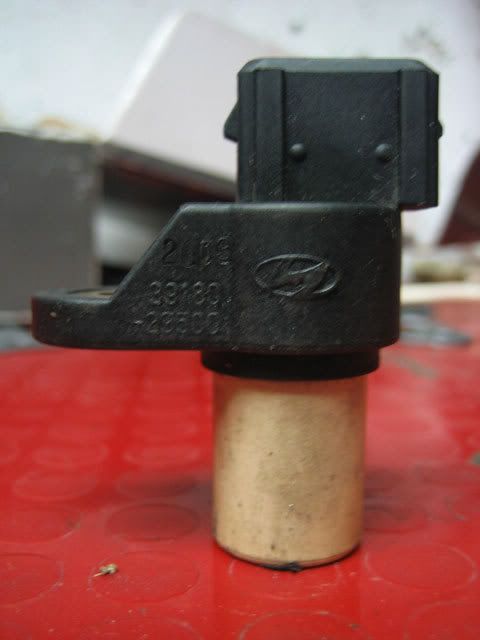
So after few problems I finaly manage to upload same 029q2 code and engine started - this time I used scope to check crank sensor input - output at first was looking similar as VR sensor but when I magnified it , there was no negative half-period, only positive and it was triangle shaped :shock:

On more shock because I logicaly enabled VR input on-board as few people already convinced me that VR sensor was mounted 100% on this particular Hyundai engine - I asked them why this inductive pick-up has one wire for 12V power then...and why there was no negative half-period as expected with ordinary inductive pick-up sensors...they wasn't so shure any more...and I was very, very angry :evil:

To cut the long story - I have few stupid questions because unfortunately I can't found anywhere some more info:

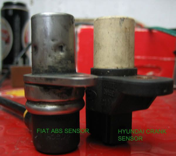
- is it possible that this crank sensor is in fact Hall-effect sensor - after all it has three wires, one is for 12V power supply, but crank wheel should have 60-2 magnetic wheel then?

- if it is Hall effect, I should modify pcb for opto input if i am corrcet?

- if it is VR sensor, why can't I rev it past 2500 RPM no matter what I do, I checked all sensor connections, ground shields, spark settings, rev & launch control settings, muliturn pot settings, everything I could think of and again nothing...I am not going to give up but for now I don't have any ideas,...please help.

- is it possible to use some robust substitute instead VB921 driver for powering directly very low resistance coils - some powerful high voltage Darlington transistors with at least 200W / 16 A min rating?


P.S.
I don't think it's code related because same 029q2 code on stimulator works perfectly in wasted spark mode.
Last edited by Bubba Zanetti on Wed Dec 13, 2006 3:10 pm, edited 1 time in total.
- Fiat Tipo 1.6 SOHC turbo (9.5:1 CR @ 1bar),
- Hyundai Accent 2.0 16V NA,
- Fiat Tipo 2.0 16V turbo 4x4 (Auto-X)
- 2001 NB Miata 1.6 turbo
- MK3 Fiesta 1.6 Turbo

******* My success story *******
http://www.msefi.com/viewtopic.php?t=20622
slow_hemi6
Super MS/Extra'er
Posts: 4122
Joined: Fri May 07, 2004 3:33 am
Location: Australia

Post by slow_hemi6 »

If it fired up and idled then there can't be much wrong with the trigger.If it is a hall it will probably have 3 wires and you should be able to keep the output at a stable state when a tooth is under the sensor and when the tooth is not under the sensor you should get the other state.
You did not say how much dwell you had been running.I think people are finding too much dwell to be death to the vb921's also.
Find the Manuals up top under Quick links: Manuals. :RTFM:
Cheers Luke
jsmcortina
Site Admin
Posts: 39622
Joined: Mon May 03, 2004 1:34 am
Location: Birmingham, UK
Contact:

Post by jsmcortina »

The problem with a power darlington is that it will generate even more heat. The VB921 has a fairly low voltage drop (Rds on) whereas a typical darlington might have 1v drop.

If you supply too much dwell you'll reach a high current.
Remembering that P = I2 R your darlingtons can get very very hot unless you build in some current monitoring and clamping.

I have a feeling that your problem is erratic wheel decoding due to the sensor and input conditioning.
How do the LEDs on the case look? If one of the outer LEDs is "sticking" then you have a recipe for disaster - they MUST flash evenly during crank and run.

James
I can repair or upgrade Megasquirts in UK. http://www.jamesmurrayengineering.co.uk

My Success story: http://www.msextra.com/forums/viewtopic ... 04&t=34277
MSEXTRA documentation at: http://www.msextra.com/doc/index.html
New users, please read the "Forum Help Page".
Bubba Zanetti
Helpful MS/Extra'er
Posts: 60
Joined: Tue Dec 14, 2004 3:58 pm
Location: Croatia
Contact:

Post by Bubba Zanetti »

2 slow_hemi6:

I finaly founded some more info about sensor:

Image

According to this picture, this is VR sensor that has three wires - two should be for inductive pick-up coil (+ and -) and one is for cable shielding that is logicaly grounded - looking at this picture it seems that's not a hall sensor after all - ordinary inductive VR sensor.

But I also found this picture - also Hyundai Coupe 2.0 ECU wiring schematic but from some other site :

Image

Now what's intersting on this picture , camshaft & crankshaft sensors are number 174 & 288 - and both sensors have pins 2 & 3 connected to ECU input but pin 1 is connected directly to +12V supply, and that's what I have measured with DMM on actual car...is this schematic that I have to follow then? It seems so...but I 'm not really sure.

Because why should VR inductive pick-up need 12V supply then ? Is it possible that it has some miniature internal conditioning circuit inside?


2 jsmcortina:

Yes, I am aware about heat dissipation problems - hey, I was DIY-ing single-ended audio amplifiers :lol: - but I would rather put darlingtons on enormuous heatsinks if that would give me more reliability.

Hmmm, I must admit that I didn't looked VB921 datasheet very throughly , but I'm wondering if it's possible to connect paralel two VB drivers to get more current - because if it's possible somehow, double drivers should have 15 Amps total current limit , at least in theory.

I even measured current draw on one coil when engine was working at 1200 RPM - I turn on peak& hold function on DMM to get close approximation and get nice 6.5 Amps :shock:

That's just 1 Amp short of current protection circuit ... and that was with 2.2 mS dwell.

About dwell - with two VB921 in my instalation I used basic settings that are mentioned in MS V3.0 manual:

cranking dwell 6.0mS
running dwell 2.2mS
minimal discharge time 0.1mS

ign output : inverted

LED 17 & 19 as spark output A & B
1k pullup resistors between cathodes and +5V

Then I played with running dwell settings : going to 3.5mS didn't change a thing, and under 2.0mS car stalled...VB drivers went hot so quickly when car was idling that I didn't have a lot of chance to register it - it was unfortunately already too late.

I also think that erratic and strange behaviour is connected to ignition input circuit - on stim everything works perfectly, and in car nothing works except I can start the car and let it idle :D

Hmm, yes I think that in some particular moment one of the LED flickered strangely few times and then stayed on for a moment and then it again worked OK, but I uploaded again fresh code and it seems that helped a bit - but I am very concerned why that happened, beacuse I can't obviously watch for LEDs all the time and reflashing codes 10 times per day...maybe some "old faithfull" code version will help...or it's "just" hardware related problem :evil:
- Fiat Tipo 1.6 SOHC turbo (9.5:1 CR @ 1bar),
- Hyundai Accent 2.0 16V NA,
- Fiat Tipo 2.0 16V turbo 4x4 (Auto-X)
- 2001 NB Miata 1.6 turbo
- MK3 Fiesta 1.6 Turbo

******* My success story *******
http://www.msefi.com/viewtopic.php?t=20622
bobnova
Helpful MS/Extra'er
Posts: 53
Joined: Wed Oct 19, 2005 10:45 pm

Post by bobnova »

On the coils, what about a high wattage 1 ohm resistor wired in series with the coil? Make it a 1.7ohm coil instead of .7.

On the VB921's frying, are you certain the inverted output is correct?
I have no idea whether it is or not, just that on my installation if i have that setting set wrong the ignitor gets hot in a hurry.


You could i suppose use +12v as shielding, but it seems odd to me.
So does a triangle for a scope pattern of the sensor, for that matter, donno whats going on there.


I have very limited MS knowlage, and even more limited Hyundai knowlage, but those are a couple things that came to mind.
'89 Honda Prelude 2.0SI 4ws
'76 Triumph TR7 fhc, soon to have ITB's and MSnS-e
Bubba Zanetti
Helpful MS/Extra'er
Posts: 60
Joined: Tue Dec 14, 2004 3:58 pm
Location: Croatia
Contact:

Post by Bubba Zanetti »

2 bobnova:

Yes, I even tried the trick with resistors - tried with 1, 2.2 & even 4.7 Ohm resistors - with first two spark was so weak that it immediately missfired, and with 4.7 Ohm engine didn't want to start .

Inverted output was turned on, 100 % sure - I first enabled that and adjusted dwell settings as stated in MS V3.0 manual before starting the car.

I read MS manual at least dozen times, but again, maybe I missed something else very important beside dwell & ignition output settings that causes burning ignition drivers that I am not aware of it - is there some other setting related to that ?

I can't see how can I use +12V as shielding - if my electronic knowledge is correct , cable shielding is working on so-called "Faraday cage principle" so you can only ground it .

I have one idea - to create triangle shaped *.wav file that simulates 60-2 wheel , as much similar as original waveform found on Hyundai crank position sensor - and then to check behaviour on Megasquirt plugged on test table.

Maybe MS V3.0 VR conditioning circuit can't cope with such strange waveform, so I'll try optical input to see is there any difference.

If nothing above mentioned would work I have easiest solution - I'll throw away Hyundai sensor and mount some familar VR sensor - that always works :D
- Fiat Tipo 1.6 SOHC turbo (9.5:1 CR @ 1bar),
- Hyundai Accent 2.0 16V NA,
- Fiat Tipo 2.0 16V turbo 4x4 (Auto-X)
- 2001 NB Miata 1.6 turbo
- MK3 Fiesta 1.6 Turbo

******* My success story *******
http://www.msefi.com/viewtopic.php?t=20622
jsmcortina
Site Admin
Posts: 39622
Joined: Mon May 03, 2004 1:34 am
Location: Birmingham, UK
Contact:

Post by jsmcortina »

1k pullup resistors between cathodes and +5V
Why?

James
I can repair or upgrade Megasquirts in UK. http://www.jamesmurrayengineering.co.uk

My Success story: http://www.msextra.com/forums/viewtopic ... 04&t=34277
MSEXTRA documentation at: http://www.msextra.com/doc/index.html
New users, please read the "Forum Help Page".
Bubba Zanetti
Helpful MS/Extra'er
Posts: 60
Joined: Tue Dec 14, 2004 3:58 pm
Location: Croatia
Contact:

Post by Bubba Zanetti »

2 jsmcortina:

Sorry, I obviously wasn't very clear with pull-up resistors:

At first when I was testing wasted spark with two VB921's , then I didn't use pull-up resistors.

But when one VB driver died, and I decide to use external Magnetti Marreli 7-pin modules for driving two double coils then I used this schematic for driving modules:

http://www.msextra.com/manuals/MS_Extra ... ut5V22.GIF


Is that correct wiring for driving external modules or I missed something?

I tried such setup and it worked very well on my friend's megasuirted car, without any ignition related problem, though he has older 026i code with MS 1 V2.2 but that shouldn't make any difference .
- Fiat Tipo 1.6 SOHC turbo (9.5:1 CR @ 1bar),
- Hyundai Accent 2.0 16V NA,
- Fiat Tipo 2.0 16V turbo 4x4 (Auto-X)
- 2001 NB Miata 1.6 turbo
- MK3 Fiesta 1.6 Turbo

******* My success story *******
http://www.msefi.com/viewtopic.php?t=20622
slow_hemi6
Super MS/Extra'er
Posts: 4122
Joined: Fri May 07, 2004 3:33 am
Location: Australia

Post by slow_hemi6 »

Well that poses a problem or two.If you are certain that both those diagrams are for hyundai coupes then what you are looking at is different year cars having different ecu's.This is obvious because the first sensor connects to ecu pins 16 and 43.In the second ecu diagram the sensors conect to pins 27 & 29 for one and 72 & 30 for the other.You say you have 12V at your connector so I would assume that diagram 2 is correct but you would need to be sure.Do not assume that it is a VR because it might not be at all.
I for one would sure like to see some scope pictures of what the sensor puts out. Do you know what component 45 is?
Find the Manuals up top under Quick links: Manuals. :RTFM:
Cheers Luke
Bubba Zanetti
Helpful MS/Extra'er
Posts: 60
Joined: Tue Dec 14, 2004 3:58 pm
Location: Croatia
Contact:

Post by Bubba Zanetti »

2 slow_hemi 6:

Biggest problem is that particular car isn't in my town unfortunately - so I have some difficulties with measuring sensor output on scope.

But yesterday I finaly manage to get hold of that particular Hyundai crank position sensor - it looks like this:

http://img.photobucket.com/albums/v358/ ... sensor.jpg

It has 3-wire connector and when trying to measure with DMM all pin combinations (pin 1-2, 1-3, 2-3 and reverse polarity) gave me more then 1Mohm resistance :shock:

I couldn't find any pin combination with some reasonably low coil resistance , something common on VR sensors like 500-1200 Ohm ... so it seems that this isn't VR sensor afterall. :(

But I suddenly remember that I saw somewhere Fiat ABS sensor that looks very , very familiar on the outside , so I searched and found it and when comparing it with Hyundai they are almost the same - great news !

This is pic of both sensors together - they indeed look very similar:

http://img.photobucket.com/albums/v358/ ... sensor.jpg

All important dimensions are the same - length from mounting flange to the top, distance from mounting hole to the center axis, even the connector is exactly same.

I also measured it with DMM and it of course is std VR type , with 530 Ohm coil resistance.

So my newest idea is to use this Fiat ABS sensor instead - it should mount without problems on Hyundai gearbox, distance from toothed wheel should be the same and it is 100% VR type so I can use VR conditioning circuit on MS V3.0 board that I already enabled without problems hopefully.


Next week I am probably going to try mounting that sensor and finaly tune the bloody car on dyno - can somebody gave me any advice what should I prepare before for quick & painless installation and tuning ?

Maybe I should bring some more shielded cable for VR sensor and try different cable routing to avoid eventual noise issues?

Can large capacitor connected between +12V and ground of the coilpack help ?

Please, any advice would be appreciated ...
- Fiat Tipo 1.6 SOHC turbo (9.5:1 CR @ 1bar),
- Hyundai Accent 2.0 16V NA,
- Fiat Tipo 2.0 16V turbo 4x4 (Auto-X)
- 2001 NB Miata 1.6 turbo
- MK3 Fiesta 1.6 Turbo

******* My success story *******
http://www.msefi.com/viewtopic.php?t=20622
sportage4x4
Experienced MS/Extra'er
Posts: 341
Joined: Tue Jan 04, 2005 6:29 pm
Location: Richmond Hill, Ontario, Canada

Post by sportage4x4 »

i'm pretty sure you are not supposed to use pullup resistors on the LED's AND inverted spark ouput. if you drive the vb921's directly from the cpu via a 330R then you use inverted. else if you drive the vb921's from the led then you use non-inverted.

that is why you have erratic rpm signal and cooked vb921s
1990 Mazda Miata: GM Gen3 V8 swap, 4.8L, custom cam, 2x GT2860R turbos, MS3 + MS3X.
2003 Kia Rio wagon: Mazda B6T/G25MR swap, Miata CAS, IHI RHF5 @ 2bar, LSx truck coils, P&H board, boost control.
slow_hemi6
Super MS/Extra'er
Posts: 4122
Joined: Fri May 07, 2004 3:33 am
Location: Australia

Post by slow_hemi6 »

He only put the pull ups on after killing the VB's in order to fire a different external module.
Find the Manuals up top under Quick links: Manuals. :RTFM:
Cheers Luke
Bubba Zanetti
Helpful MS/Extra'er
Posts: 60
Joined: Tue Dec 14, 2004 3:58 pm
Location: Croatia
Contact:

Post by Bubba Zanetti »

2 sportage 4x4:

Slow-hemi 6 is right - I used pull-up resistors only after I already destroyed VB's, together with external ignition modules.


I have 2 good reasons to think that my problem is ignition input related:

1. I checked throughly same MS board few hours before instalation on Hyundai on stimulator with wav file on VR input as simulation of 60-2 wheel - MS recognized input without problems , anywhere from 120 to more than 10 000 RPM, I even connected two double coils on my testing table powered with external modules that I used later on actual instalation - spark was strong and stable on all 4 spark plugs, on all RPMs,


This is pic where I am testing two double coils with VR input:

http://upload.killercivic.com//files/2/PB050062.JPG


And this are 4 spark plugs on 7500 RPM:

http://upload.killercivic.com//files/2/PB050066.JPG


2. Few days later , I installed another MS 1 V3.0 board on Fiat 2.0 16V turbo engine - it was very similar wasted spark setup , with std Fiat 2-wire VR sensor connected to VR input - only difference is 4-1 wheel instead 60-2 - and it worked immediately - and engine can rev normaly, unlike Hyundai engine , that hits "wall" at about 2400-2500 RPM.
- Fiat Tipo 1.6 SOHC turbo (9.5:1 CR @ 1bar),
- Hyundai Accent 2.0 16V NA,
- Fiat Tipo 2.0 16V turbo 4x4 (Auto-X)
- 2001 NB Miata 1.6 turbo
- MK3 Fiesta 1.6 Turbo

******* My success story *******
http://www.msefi.com/viewtopic.php?t=20622
sportage4x4
Experienced MS/Extra'er
Posts: 341
Joined: Tue Jan 04, 2005 6:29 pm
Location: Richmond Hill, Ontario, Canada

Post by sportage4x4 »

i had this same wall thing happen on my kia. it was to do with the wiring of the tach input circuit. you have a hall sensor, how are you getting the signal to the cpu? i used the opto isolator (v2.2) but brought the 5v pullup from the same resistor as the cpu irq pin pullup. i think when i had that rpm wall problem it was triggering on the wrong edge of the tooth on the flywheel
1990 Mazda Miata: GM Gen3 V8 swap, 4.8L, custom cam, 2x GT2860R turbos, MS3 + MS3X.
2003 Kia Rio wagon: Mazda B6T/G25MR swap, Miata CAS, IHI RHF5 @ 2bar, LSx truck coils, P&H board, boost control.
Bubba Zanetti
Helpful MS/Extra'er
Posts: 60
Joined: Tue Dec 14, 2004 3:58 pm
Location: Croatia
Contact:

Post by Bubba Zanetti »

The problem is solved :D


Last weekend I managed to start and rev car without problems, missfires or backfires to the 8500 RPM - it runs!


To bring some more details if somebody is more interested in setup:

1. first I removed strange Hyundai crank sensor and put Fiat ABS VR sensor, as I already mentioned - like I checked before - it was bolt-on modification, thanks God!

2. then I use good quality microphone shielded cable cca. 3m long and use it as signal cable for that VR sensor - to avoid possible problems with noise in OEM Hyundai cable just in case,

3. to prevent possible noise in ignition outputs - for two ignition outputs (Spark A & B) from MS I used stereo shielded cable, all the way from MS directly to external ignition modules - cable was grounded only on MS end, just like VR sensor cable of course,

4. I put 20uF / 100V capacitor as close to the double coils as possible : one pin to the +12V supply and another pin on valve cover near coils - hopefully that can only help with resets, as I read over this forum.

After all this mods , then I uploaded old 026i MSnS-extra code - to avoid possible problems with 029q2 code.

With old code uploaded , I made totally new *.msq file from scratch: both fuel and spark maps , wheel decoder setttings - evertyhing from scratch - check everything couple times before starting engine.

And then tried to start the car - nothing, not even one cycle :?

Hmm, then I check "realtime display" in Megatune to see eventual voltage drop - it was around 9V when cranking - and MS resets about 12 times in a row...so I placed new car battery...

With new battery - again voltage drop - OK, I thought that maybe ground point on chassis has some resistance - so I used new power lines - battery was already relocated in the trunk few months ago - so I used 25mm2 car stereo cable as +12V supply directly from battery to MS relays and similar cable for ground - also directly from battery...

Then I had good voltage (around 11V on cranking) but I got something else - corrupted code - first all leds stayed on, then all off, then one was flashing, then another flashes ...and so on, and on ...

I uploaded another code - this time 029T code and again code corrupted whenever I tried to crank the car ... I had a lot of patience and uploaded 029T code one more time - and bingo, I get normal LED17 & LED 19 flashing , like they suppose to flash...

With little tweaking of the VR circuit pots , I've got good VR signal and car started but on two cylinder only - fortunately after little investigation with scope, it wasn't MS failure - it was loose wire on one ignition module.:lol:

After that - car started immediately and the magic wall at 2500 RPM was gone - that Hyundai engine can really rev 8)
- Fiat Tipo 1.6 SOHC turbo (9.5:1 CR @ 1bar),
- Hyundai Accent 2.0 16V NA,
- Fiat Tipo 2.0 16V turbo 4x4 (Auto-X)
- 2001 NB Miata 1.6 turbo
- MK3 Fiesta 1.6 Turbo

******* My success story *******
http://www.msefi.com/viewtopic.php?t=20622
Olivier
MS/Extra Newbie
Posts: 21
Joined: Wed Jan 17, 2007 3:22 am

Post by Olivier »

Hey.

First i wil say that this megasquirt is a whole new area for me...

I have the exact same problem as you describe...
When i start i 1st gear i can run to about 2500rpm without any problems.
but from 2500-3000 rpm it misfires, and it misfire very badly - all gauges are out of control... just like yours.
But i can drive 1st to 2400rpm, 2nd to 2400rpm, 3rd to 2400rpm and then go to 2nd (now it's over 3000rpm) and then theres no problem at all...

Can you say enything about what you think solved the problem?

Your setup is also very similar to mine.
My setup:

Subaru impreza 2.0 sti engine from 98.
MS1 V.3 board with same ignition drivers
Inductive tach-sensor and 12-1 crankwheel.


The engine has driven with megasquirt before but with the older version af the box...

My reasonable sens says me that if it where the trigger signal it whould f*** it up the whole way, not just between 2500rpm and 3000rpm. I
shouldn't even could start the engine if the trigger was fucked...

Hope you or somebody else can help me... :|

Oliver

Sorry if my english is a little bad, but i'm from denmark so... :oops:
Olivier
MS/Extra Newbie
Posts: 21
Joined: Wed Jan 17, 2007 3:22 am

Post by Olivier »

Hey again.

I took a log from a little drive this evening.

Hope somebody wants to take a look to see if theres anything unusual and maybe have a clue what to do about it....

The only thing i have noticed is in row 99. the rpm drops from 2218 to 802 but i cant se if any of the other sensors etc thats going crazy...

I really want my car to run like a dream, but it is a little difficult when something is wrong and i havent got a clue what it is...

Oliver
Bubba Zanetti
Helpful MS/Extra'er
Posts: 60
Joined: Tue Dec 14, 2004 3:58 pm
Location: Croatia
Contact:

Post by Bubba Zanetti »

2 Olivier:

Hi,


I'll try to help you if possible, but if you read my last post you can easily see that last day when I played with Hyundai I had to do quite few modifications at ONCE prior solving my problem - because I just didn't have time to slowly change something and see if there were some results - angry customers were litteraly behind me, breathing on my neck and were very, very pissed and were seriously thinking about ditching complete MS instalation if I don't start & finaly tune bloody car in next few hours :D

- I put another VR sensor, connected 20uF/100 V condenser on coil packs, instaled new shielded wires on MS ignition outputs & VR sensor and re-routed wires to another positions far away from possible sources of noise, then I did quite a few MSnS-Extra firmware updates, changing +12V supply cables, changed grounding points...so unfortunately I am not really sure what was crucial for eliminating my "2500 RPM wall" - I believe that new VR sensor played a very big role, but again - maybe it's combination of some other factors. :?


You forgot to mention what MSnS-Extra code were using - did you try to upload 029v code ?

Lately when I was doing various MS instalations I played a lot with 029q2, 029s and 029t code , both on stim and in actual cars to see eventual ignition problems in wasted spark mode - and found very recently that most stable working code is 029v, all others worked but always with some glitches and some strange behaviour.


I looked at yout datalog - to me it looks clean, without almost any problems, except at few points were RPM droped from 2400-2500 RPM to 800 RPM - as you already described.


It's a pitty that I forgot to record even one loussy datalog when I had "issues" with my Hyundai MS instalation - then we could maybe compare our two datalogs and maybe could find some similarities...
:RTFM:
- Fiat Tipo 1.6 SOHC turbo (9.5:1 CR @ 1bar),
- Hyundai Accent 2.0 16V NA,
- Fiat Tipo 2.0 16V turbo 4x4 (Auto-X)
- 2001 NB Miata 1.6 turbo
- MK3 Fiesta 1.6 Turbo

******* My success story *******
http://www.msefi.com/viewtopic.php?t=20622
Olivier
MS/Extra Newbie
Posts: 21
Joined: Wed Jan 17, 2007 3:22 am

Post by Olivier »

I have just found out that the signals peak is about 32v an in idle the signal is about 16v. i mesured it with a scope...
After a bit of reading i have done the conklusion that the vr in is not strong enough...

Now im gonna try to put a clamp with two dioder( dont know wahts it called in english, but the ones that only can send the voltage one way.)between ground and the signal, couse that should take the maximum input to about 0.6v and it should do it...

Do anyone disagree in that?

It is one of my friends that maked that suggestion (he is an electronic geek).

Please come with a answer if it's totally crazy...

Oliver
Olivier
MS/Extra Newbie
Posts: 21
Joined: Wed Jan 17, 2007 3:22 am

Post by Olivier »

I run a version of 029q
Post Reply