Following a conversation with mad max, I have designed a small board which has 2 LM1815 VR conditioner circuits and 2 ADC conditioner circuit. The VR circuit also has a jumper for pin 5 allowing it be left floating or tied to either ground or 5V to allow all LM1815 modes. The ADC circuit has the bias resistor, 2 caps, and another resistor to allow the different configurations.
The board has the same size as my p&h board (4"x1.1") and will fit in the last slot of the standard MS case. Since the components are lower than on the p&h board (no big sense resistor or big diode), the dual VR board should fit in the lower half case under the MS board. I, of course, haven't verified that since the board is only a design at this point.
This board is mainly targeted at MS V2.2 owners who want to use MS1/extra but don't want/need all the features from the error* board. It can also be used with MS2 (MS2 code, microsquirt code, MS2/extra code) and/or MS V3.0 for an additional VR input and the ADC inputs.
Before I have this board made, I wanted to know if there was any interest in such a board. If I see some interest, I'll have a batch made. The board will be about the same price as the p&h board ($18.).
Let me know what you think.
Jean
Dual VR conditioner board
Moderators: jsmcortina, muythaibxr
-
racingmini_mtl
- Super MS/Extra'er
- Posts: 9130
- Joined: Sun May 02, 2004 6:51 am
- Location: Quebec, Canada
- Contact:
Jean, I'd be interested in one of these boards if it had more than 2 ADC circuits. Maybe 4?
I was going to make a board that does exactly what you are doing, except with a few more ADC inputs. But hey, if your willing to add a few things that saves me some trouble.
I wasn't going to use the LM1815 since It will be driven by VSS sensors and they are usually a little more consistant output when compared to a regular VR. I made up a little two transistor version similar to the EZ-VR. But the LM1815 works. I would like 4 ADC inputs for fuel level, oil pressure, oil temperature and one "spare". the LCDash I will be using it on has four open ADC channels.
-
racingmini_mtl
- Super MS/Extra'er
- Posts: 9130
- Joined: Sun May 02, 2004 6:51 am
- Location: Quebec, Canada
- Contact:
Jean,racingmini_mtl wrote:Scott,
I'll see what I can do. I want to keep the board simple and don't want any feature creep but if I can make the board interesting for a wider audience and keep the same footprint then that's fine. The ADC circuit is just a few components and they don't have to be populated if not needed.
Jean
Thanks for your help, If you can't fit four ADC conditioning circuits on there, that's no problem, the circuit is easy to make in a proto area. I was just trying to make things neater. Probably in the next LCDash board spin the circuits could be included on the board, since the firmware will be set and tested, so no daughterboard will be required after that.
Also what is your ECD?
-
racingmini_mtl
- Super MS/Extra'er
- Posts: 9130
- Joined: Sun May 02, 2004 6:51 am
- Location: Quebec, Canada
- Contact:
This is what I've come up with: 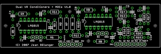
In addition to adding 2 more ADC circuits, I have added 4 holes in case the board is not to be mounted in a slot of the MS case. Also, one or two holes can be used to secure the board in place when it is mounted in the last slot of the case.
However, I won't be able to get it done if I only have a couple of interested persons. If I can get interest for 5 boards, then I'll go ahead. And I'm using Eagle to design the boards.
Cheers,
Jean
-
Peter Florance
- Super MS/Extra'er
- Posts: 3653
- Joined: Fri Apr 02, 2004 8:40 pm
- Location: Virginia Beach, VA
- Contact:
I used this circuit, but grounded pin 14 to use it in zero crossing mode.racingmini_mtl wrote:This is what I've come up with:
In addition to adding 2 more ADC circuits, I have added 4 holes in case the board is not to be mounted in a slot of the MS case. Also, one or two holes can be used to secure the board in place when it is mounted in the last slot of the case.
However, I won't be able to get it done if I only have a couple of interested persons. If I can get interest for 5 boards, then I'll go ahead. And I'm using Eagle to design the boards.
Cheers,
Jean
You might provide instructions to bridge (or replace with jumper) the capacitor that is tied to pin 14 if users want to use it that way.
Also do you have plenty of power supply bypass capacitor? The datasheet calls for it, especially if the IC is required to clamp large VR signals.
HTH
Peter
Peter Florance
PF Tuning
81 BMW Euro 528i ESP Car
60-2 Wheel LS2 Coils, Low Z Inj
Co-Driver 1999 BMW E46 DSP car.
PF Tuning
81 BMW Euro 528i ESP Car
60-2 Wheel LS2 Coils, Low Z Inj
Co-Driver 1999 BMW E46 DSP car.
-
racingmini_mtl
- Super MS/Extra'er
- Posts: 9130
- Joined: Sun May 02, 2004 6:51 am
- Location: Quebec, Canada
- Contact:
Peter,Peter Florance wrote:I used this circuit, but grounded pin 14 to use it in zero crossing mode.
You might provide instructions to bridge (or replace with jumper) the capacitor that is tied to pin 14 if users want to use it that way.
Also do you have plenty of power supply bypass capacitor? The datasheet calls for it, especially if the IC is required to clamp large VR signals.
HTH
Peter
I used this circuit as the basis for the board (2 of them):

So there is one power supply bypass capacitor for each LM1815N and according to the schematic above it should be 0.1uF and they correspond to C3 and C7 on my board. The datasheet is very generic in what is required and I'm not familiar with the typical VR sensor signal range. What did you use for your bypass capacitor and do you think 0.1uF is ok?
And thank you for the suggestion for the zero crossing mode.
Cheers,
Jean
Jean, I'll take two boards!! three to go......racingmini_mtl wrote:This is what I've come up with:
In addition to adding 2 more ADC circuits, I have added 4 holes in case the board is not to be mounted in a slot of the MS case. Also, one or two holes can be used to secure the board in place when it is mounted in the last slot of the case.
However, I won't be able to get it done if I only have a couple of interested persons. If I can get interest for 5 boards, then I'll go ahead. And I'm using Eagle to design the boards.
Cheers,
Jean
-
Peter Florance
- Super MS/Extra'er
- Posts: 3653
- Joined: Fri Apr 02, 2004 8:40 pm
- Location: Virginia Beach, VA
- Contact:
I suspect .1uf is large enough for most applications. I was having some issues that ended up not being caused by the Vr conditioner and used 10uf in parallel with .1uf.racingmini_mtl wrote:Peter,Peter Florance wrote:I used this circuit, but grounded pin 14 to use it in zero crossing mode.
You might provide instructions to bridge (or replace with jumper) the capacitor that is tied to pin 14 if users want to use it that way.
Also do you have plenty of power supply bypass capacitor? The datasheet calls for it, especially if the IC is required to clamp large VR signals.
HTH
Peter
I used this circuit as the basis for the board (2 of them):
So there is one power supply bypass capacitor for each LM1815N and according to the schematic above it should be 0.1uF and they correspond to C3 and C7 on my board. The datasheet is very generic in what is required and I'm not familiar with the typical VR sensor signal range. What did you use for your bypass capacitor and do you think 0.1uF is ok?
And thank you for the suggestion for the zero crossing mode.
Cheers,
Jean
Peter Florance
PF Tuning
81 BMW Euro 528i ESP Car
60-2 Wheel LS2 Coils, Low Z Inj
Co-Driver 1999 BMW E46 DSP car.
PF Tuning
81 BMW Euro 528i ESP Car
60-2 Wheel LS2 Coils, Low Z Inj
Co-Driver 1999 BMW E46 DSP car.
-
racingmini_mtl
- Super MS/Extra'er
- Posts: 9130
- Joined: Sun May 02, 2004 6:51 am
- Location: Quebec, Canada
- Contact:
Ok, I have enough interest to have the board made. I made one final small tweak: I added a ground connection for the ADC circuits so that if in someone's installation the ADCs have their own ground you can just keep it separate from the VR sensors. In most installs you're just going to tie them together but that gives more flexibility and allows to keep the ADC signals cleaner if the VR signals are noisy.
This is what it looks like: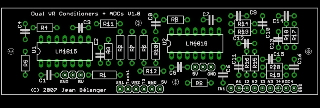
The only difference with the previous one is at the bottom right.
The boards are going to be US$18 (bare board) and shipping will be $3 for US/Canada and $5 for everywhere else. I only take Paypal for payment. The boards should be in my hands in about 2 weeks and I can them immediately ship them.
Cheers,
Jean
-
mad max
- Helpful MS/Extra'er
- Posts: 52
- Joined: Mon Sep 20, 2004 10:49 am
- Location: ste-marcelline,Québec ,cnd
I'll take two boards!
msnse pontiac fiero v6 3.1l
msnse1.6l sohc 16v turbo suzuki samurai
http://www.qcswiftclub.com/forum/viewtopic.php?t=3710
msnse1.3l dohc 16v suzuki samurai
ms2extra dohc 16v suzuki samurai
msnse1.6l sohc 16v turbo suzuki samurai
http://www.qcswiftclub.com/forum/viewtopic.php?t=3710
msnse1.3l dohc 16v suzuki samurai
ms2extra dohc 16v suzuki samurai
-
racingmini_mtl
- Super MS/Extra'er
- Posts: 9130
- Joined: Sun May 02, 2004 6:51 am
- Location: Quebec, Canada
- Contact:
Ok. The boards are on their way here. I should have them in a couple of days (which mean effectively Monday or Tuesday at the latest).
So if you want your boards as soon as possible, you can pay me now and I'll be able to ship the boards as soon as I have them in hand. By the way, the shipping cost mentioned above is not per board but for up to 4 boards.
My paypal address is "boards at jbperf.com".
Cheers,
Jean
So if you want your boards as soon as possible, you can pay me now and I'll be able to ship the boards as soon as I have them in hand. By the way, the shipping cost mentioned above is not per board but for up to 4 boards.
My paypal address is "boards at jbperf.com".
Cheers,
Jean
-
Peter Florance
- Super MS/Extra'er
- Posts: 3653
- Joined: Fri Apr 02, 2004 8:40 pm
- Location: Virginia Beach, VA
- Contact:
To me it's simpler than using the IC's built-in one-shot. All I need is a zero-crossing detector; I was afraid that any additional feature was potentially something I would have to troubleshoot (on a noisy BMW race car that was not street legal and a hassle to troubleshoot)newtyres1 wrote:Peter,Peter Florance wrote:I used this circuit, but grounded pin 14 to use it in zero crossing mode. You might provide instructions to bridge (or replace with jumper) the capacitor that is tied to pin 14 if users want to use it that way
Are there some advantages in using it in this mode?
Ian.
In the end it probably would have worked either way, but in this mode I was able to cleanly log RPM to 9300 rpm on 60-2 wheel (after unfortunate downshift 'incident').
Peter Florance
PF Tuning
81 BMW Euro 528i ESP Car
60-2 Wheel LS2 Coils, Low Z Inj
Co-Driver 1999 BMW E46 DSP car.
PF Tuning
81 BMW Euro 528i ESP Car
60-2 Wheel LS2 Coils, Low Z Inj
Co-Driver 1999 BMW E46 DSP car.
-
newtyres1
- Master MS/Extra'er
- Posts: 632
- Joined: Mon Feb 06, 2006 8:32 pm
- Location: Brisbane, Australia
Thanks for that Peter, I wasn't aware of that mode, I think the datasheet expects you to know that that is how it can operate, or maybe I didn't study it enough to fully understand.
Jean, just a suggestion for your board, would it be worth having the 2 LM1815 ccts completely seperate on the PCB so a user could saw the board in half if required, with 1 x LM on one piece and the other LM and ADC inputs on the other? For myself, who only needed one LM1815, I could cut the board up and bolt the one LM cct to the lid and use up minimal space, and have a spare LM1815 board for another project or a friend in need. Just adding versatility, just a thought...I see you are running out of room and designing takes a long time though. Oh yeah, thanks for designing the board in the first place, and I hope a few home brew veroboard LM1815 ccts get updated to your board for the sake of reliability at least.
Ian.
-
racingmini_mtl
- Super MS/Extra'er
- Posts: 9130
- Joined: Sun May 02, 2004 6:51 am
- Location: Quebec, Canada
- Contact:
Ian,newtyres1 wrote:Thanks for that Peter, I wasn't aware of that mode, I think the datasheet expects you to know that that is how it can operate, or maybe I didn't study it enough to fully understand.
Jean, just a suggestion for your board, would it be worth having the 2 LM1815 ccts completely seperate on the PCB so a user could saw the board in half if required, with 1 x LM on one piece and the other LM and ADC inputs on the other? For myself, who only needed one LM1815, I could cut the board up and bolt the one LM cct to the lid and use up minimal space, and have a spare LM1815 board for another project or a friend in need. Just adding versatility, just a thought...I see you are running out of room and designing takes a long time though. Oh yeah, thanks for designing the board in the first place, and I hope a few home brew veroboard LM1815 ccts get updated to your board for the sake of reliability at least.
Ian.
I'll think about it for a next version and see if it's not too difficult..
But, since the 2 LM1815 circuits are independent on the board as it is, you could actually do it with this board. If you look at the picture of the board, you could separate the board between R2 and R7 and you'd have 1 LM1815 on the left and the rest on the right. There is even a 5V and a ground connection available. You'd have to connect the output of the circuit to R11 and you might want to add another hole for holding the board but there is space between R1 and my name.
Jean
-
racingmini_mtl
- Super MS/Extra'er
- Posts: 9130
- Joined: Sun May 02, 2004 6:51 am
- Location: Quebec, Canada
- Contact:
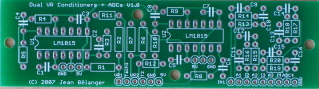
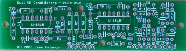
I have received the boards and I have sent the boards to those who have sent their payment. This is a picture of the board (click on the pic for a bigger version):
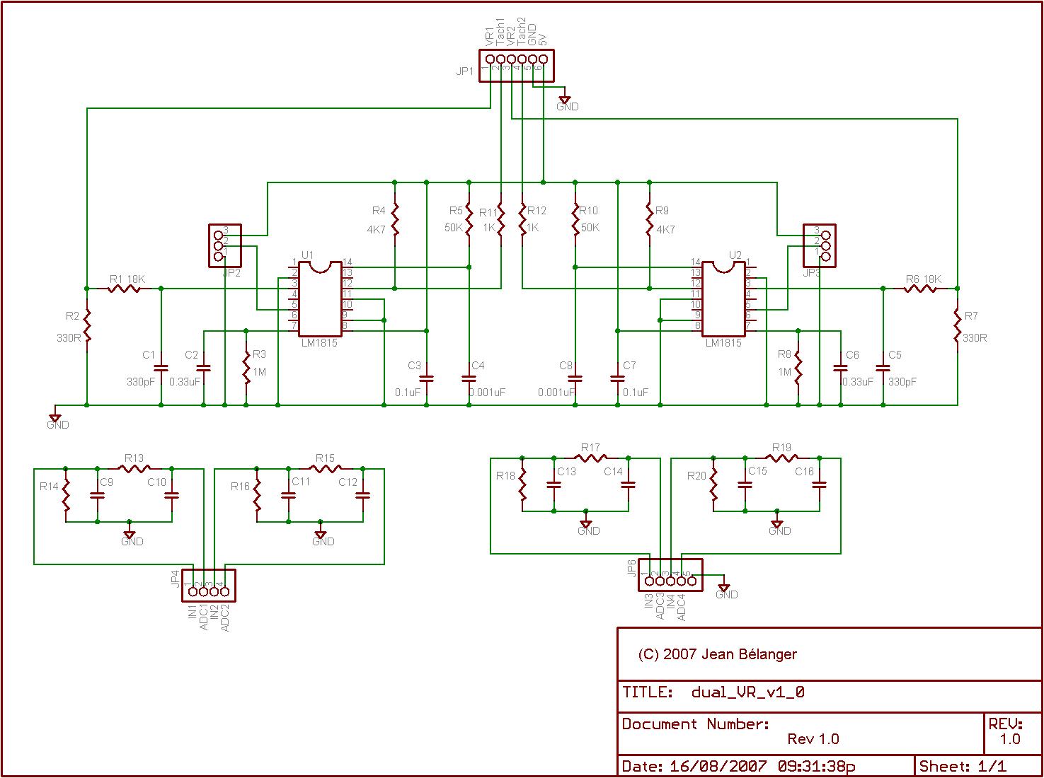
The schematic of the board is here (again click on the pic for a larger version):

Please note that R1, R2, R6, R7 are 1/4W resistors which means they are on a 0.4" pad spacing and all other resistors are 1/6W resistors which means they are on a 0.3" pad spacing. The capacitors are all on a 0.2" pad spacing.
The BOM given in the MSextra manual gives Digikey part numbers for 1/4W resistors and not all the capacitors have the correct lead spacing so be careful to verify this before ordering parts. I'll have a more complete BOM soon but for now the resistors needed have part numbers that finish by QBK-ND for the 1/4W while the 1/6W part numbers finish by EBK-ND. Please contact me if you need the part numbers before I have posted them.
Also, be aware that the values shown on the schematic for R5, C4, R10, C8 may need to be adjusted depending on the mode chosen, the wheel type, and the target RPM. Also, R2, R7, R10, R11 may not be needed (or may need different values) depending on the VR sensor type (R2,R7) or if the VR circuit is directly connected to th CPU or not (R10,R11). R1 and R6 may also need to be changed to a new value depending on the VR sensor. All these are explained in more detail in the LM1815 datasheet.
The resistor and capacitor values for the ADC circuits will need to be determined depending on the sensor type used. Copy the values used on the MS schematics for the sensor used. In most cases, not all components will be needed.
I'll post here and on my site the additional information on the part numbers.
Cheers,
Jean
The schematic of the board is here (again click on the pic for a larger version):
Please note that R1, R2, R6, R7 are 1/4W resistors which means they are on a 0.4" pad spacing and all other resistors are 1/6W resistors which means they are on a 0.3" pad spacing. The capacitors are all on a 0.2" pad spacing.
The BOM given in the MSextra manual gives Digikey part numbers for 1/4W resistors and not all the capacitors have the correct lead spacing so be careful to verify this before ordering parts. I'll have a more complete BOM soon but for now the resistors needed have part numbers that finish by QBK-ND for the 1/4W while the 1/6W part numbers finish by EBK-ND. Please contact me if you need the part numbers before I have posted them.
Also, be aware that the values shown on the schematic for R5, C4, R10, C8 may need to be adjusted depending on the mode chosen, the wheel type, and the target RPM. Also, R2, R7, R10, R11 may not be needed (or may need different values) depending on the VR sensor type (R2,R7) or if the VR circuit is directly connected to th CPU or not (R10,R11). R1 and R6 may also need to be changed to a new value depending on the VR sensor. All these are explained in more detail in the LM1815 datasheet.
The resistor and capacitor values for the ADC circuits will need to be determined depending on the sensor type used. Copy the values used on the MS schematics for the sensor used. In most cases, not all components will be needed.
I'll post here and on my site the additional information on the part numbers.
Cheers,
Jean
-
racingmini_mtl
- Super MS/Extra'er
- Posts: 9130
- Joined: Sun May 02, 2004 6:51 am
- Location: Quebec, Canada
- Contact: