I am going to try and build a VSS circuit on the proto area of my v1.5 DIYPnP. I plan to use the circuit described Here
http://msextra.com/doc/ms1extra/antirev.html.
I have been looking for part numbers but I am not sure about the type of capacitors and diodes. If anyone could help fill in the blanks, it would be appreciated.
DIYPnP VSS circuit
Moderators: jsmcortina, muythaibxr
DIYPnP VSS circuit
'94 Miata ; 2001 VVT engine; DiyPnp 3.3.2 & VVTuner , 99-00 crank & cam sensors; sequential Toyota COP ignition; LC-1 wide band O2; Square Top manifold; RB header; Custom CAI.
-
SymTech Laboratories
- Super MS/Extra'er
- Posts: 2188
- Joined: Sun Aug 31, 2008 4:02 pm
- Location: South Florida, USA
- Contact:
Re: DIYPnP VSS circuit
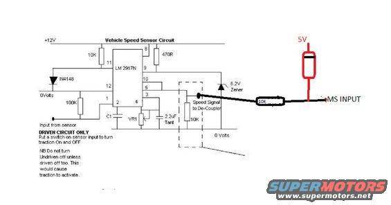
Per the schematic, C2 should be a 2.2uF tantalum capacitor. These are polarized, so pay attention to how you connect it. If you look a little below the schematic, there's a note explaining that C1 should either be a 3.3nF, 6.8nF, or 15nF capacitor, depending on how many pulses your sensor generates.
The 1N4148 diode is pretty popular and easy to find, but any small signal diode should work. The 1N4735 is a pretty popular 6.2V Zener diode, but again, just about any 6.2V Zener diode should work.
The 1N4148 diode is pretty popular and easy to find, but any small signal diode should work. The 1N4735 is a pretty popular 6.2V Zener diode, but again, just about any 6.2V Zener diode should work.

Re: DIYPnP VSS circuit
Thanks, by time you have to filter down with all the details like leg spacing temp rating it gets a little thick.
Thanks again
Graeme
Thanks again
Graeme
'94 Miata ; 2001 VVT engine; DiyPnp 3.3.2 & VVTuner , 99-00 crank & cam sensors; sequential Toyota COP ignition; LC-1 wide band O2; Square Top manifold; RB header; Custom CAI.
Re: DIYPnP VSS circuit
well, I built the circuit on a test board, and I can't seem to get it to work.
In a Miata, the speedometer provides a pulsed ground, I am assuming the ECU provides the pulls up. the FSM calls for about 7v while driving, so if it is a 50% duty thats about 14V and at 60 mph the frquency is about 68Hz.
I am using a signal generator to simulate the speed signal. but the Vout is about 1.5V no matter what the frquency. Adjusting R1 does not effect the output until it is bottomed out (zero ohms) and then the output jumps to 5.4v
Has anyone built this or a similar circuit that might have some tips for me?
Thanks,
Graeme
Last edited by GraemeD on Mon Jan 14, 2013 2:27 pm, edited 1 time in total.
'94 Miata ; 2001 VVT engine; DiyPnp 3.3.2 & VVTuner , 99-00 crank & cam sensors; sequential Toyota COP ignition; LC-1 wide band O2; Square Top manifold; RB header; Custom CAI.
Re: DIYPnP VSS circuit
I got the circuit to work, must have been my test build. I Built another on a breadboard and it worked as it should. I have a question, the output can go as high as 6.24v, is that too much for the spareAD2 ? If it is, I am going to try to make it run on 5v.
Thanks,
Graeme
Thanks,
Graeme
'94 Miata ; 2001 VVT engine; DiyPnp 3.3.2 & VVTuner , 99-00 crank & cam sensors; sequential Toyota COP ignition; LC-1 wide band O2; Square Top manifold; RB header; Custom CAI.
-
SymTech Laboratories
- Super MS/Extra'er
- Posts: 2188
- Joined: Sun Aug 31, 2008 4:02 pm
- Location: South Florida, USA
- Contact:
Re: DIYPnP VSS circuit
According to the datasheet, the chip can withstand that much voltage, but it won't be able to read it. You should adjust VR1 so the voltage is 2.5V at half your maximum speed.GraemeD wrote:I got the circuit to work, must have been my test build. I Built another on a breadboard and it worked as it should. I have a question, the output can go as high as 6.24v, is that too much for the spareAD2 ? If it is, I am going to try to make it run on 5v.
Re: DIYPnP VSS circuit
Thanks for the reply,SymTech Laboratories wrote:According to the datasheet, the chip can withstand that much voltage, but it won't be able to read it. You should adjust VR1 so the voltage is 2.5V at half your maximum speed.GraemeD wrote:I got the circuit to work, must have been my test build. I Built another on a breadboard and it worked as it should. I have a question, the output can go as high as 6.24v, is that too much for the spareAD2 ? If it is, I am going to try to make it run on 5v.
I know the LM2917 chip is okay with it, but the MS chip is the one I am worried about. If there was a failure in the VSS circuit and the voltage went high(6.2v) will that damage the MS processor?
'94 Miata ; 2001 VVT engine; DiyPnp 3.3.2 & VVTuner , 99-00 crank & cam sensors; sequential Toyota COP ignition; LC-1 wide band O2; Square Top manifold; RB header; Custom CAI.
-
jsmcortina
- Site Admin
- Posts: 39622
- Joined: Mon May 03, 2004 1:34 am
- Location: Birmingham, UK
- Contact:
Re: DIYPnP VSS circuit
Do not apply more than 5V to the Megasquirt processor.
Your design should operate over the 0-5V range. If a greater voltage can be generated in fault conditions then arrange a voltage and current limiting clamp circuit.
(e.g. a 10k series resistor and a diode to 5V.)
James
Your design should operate over the 0-5V range. If a greater voltage can be generated in fault conditions then arrange a voltage and current limiting clamp circuit.
(e.g. a 10k series resistor and a diode to 5V.)
James
I can repair or upgrade Megasquirts in UK. http://www.jamesmurrayengineering.co.uk
My Success story: http://www.msextra.com/forums/viewtopic ... 04&t=34277
MSEXTRA documentation at: http://www.msextra.com/doc/index.html
New users, please read the "Forum Help Page".
My Success story: http://www.msextra.com/forums/viewtopic ... 04&t=34277
MSEXTRA documentation at: http://www.msextra.com/doc/index.html
New users, please read the "Forum Help Page".
-
SymTech Laboratories
- Super MS/Extra'er
- Posts: 2188
- Joined: Sun Aug 31, 2008 4:02 pm
- Location: South Florida, USA
- Contact:
Re: DIYPnP VSS circuit
We were referring to the MS chip, not the LM2917. We wouldn't recommend testing the absolute maximum rating, though! Like James said, if you think it's possible more than 5V can be generated, you should take measures to limit the voltage.GraemeD wrote:I know the LM2917 chip is okay with it, but the MS chip is the one I am worried about. If there was a failure in the VSS circuit and the voltage went high(6.2v) will that damage the MS processor?
Re: DIYPnP VSS circuit
Thanks,
I will try it using 5v as the supply. it might be easier and use a couple of less resistors.
Or does the "de-coupler" accomplish this limiting?
I will try it using 5v as the supply. it might be easier and use a couple of less resistors.
Or does the "de-coupler" accomplish this limiting?
'94 Miata ; 2001 VVT engine; DiyPnp 3.3.2 & VVTuner , 99-00 crank & cam sensors; sequential Toyota COP ignition; LC-1 wide band O2; Square Top manifold; RB header; Custom CAI.
-
SymTech Laboratories
- Super MS/Extra'er
- Posts: 2188
- Joined: Sun Aug 31, 2008 4:02 pm
- Location: South Florida, USA
- Contact:
Re: DIYPnP VSS circuit
The de-coupler circuit won't limit the voltage to 5V, and supplying the LM2917 with 5V isn't a good idea. The chip probably can't operate too close to the rails, so supplying it with 5V will limit its output range.GraemeD wrote:I will try it using 5v as the supply. it might be easier and use a couple of less resistors.
Or does the "de-coupler" accomplish this limiting?
Re: DIYPnP VSS circuit
Like so ?jsmcortina wrote:Do not apply more than 5V to the Megasquirt processor.
Your design should operate over the 0-5V range. If a greater voltage can be generated in fault conditions then arrange a voltage and current limiting clamp circuit.
(e.g. a 10k series resistor and a diode to 5V.)
James
95 Probe v6-t MS1
00 Accent 2.0L-T,Ms1
14 Factory Five 818 MS2 4 ebc/meth only
03 Tiburon v6 SC 1st ever MS
93 Tracer KLDE,Compounds w/2 of everything, Twin Megasquirt ?
00 Lotus Esprit v8-TT Full MS3x/ls1 coils/water/Meth
97 200sx 1.6L Stock, MS2/3.0, Sequential, CBR1000r coils
00 Accent 2.0L-T,Ms1
14 Factory Five 818 MS2 4 ebc/meth only
03 Tiburon v6 SC 1st ever MS
93 Tracer KLDE,Compounds w/2 of everything, Twin Megasquirt ?
00 Lotus Esprit v8-TT Full MS3x/ls1 coils/water/Meth
97 200sx 1.6L Stock, MS2/3.0, Sequential, CBR1000r coils