Help with Tach Output, strange tach behavior

All questions about MS2/Microsquirt/Microsquirt module. See also MS2/Extra manuals

Moderators: jsmcortina, muythaibxr

Post Reply
BigMike
MS/Extra Newbie
Posts: 21
Joined: Mon Jul 10, 2023 7:58 pm
Location: CenCal

Help with Tach Output, strange tach behavior

Post by BigMike »

Good morning MSExtra,

Background
Searched around and didn't find help so here goes. My setup is a 1987 Toyota MR2 with PnP Gen 2 made for the normally aspirated Toyota 1.6L 4A-GE which uses a 4/1 distributor CAS and single coil ignition system, however, I am running this ECU on a Supercharged 4A-GZE (C.A.R.B.-approved engine conversion from a US-spec 1988 Supercharged MR2) which has a different ignition system whereby a 24/2 dizzy CAS is used, and in my MegaSquirt install, I am using full sequential spark with 4x smart coil on plug (as well as full sequential and re-wired injectors) using the Dual Wheel trigger arrangement with external AXM-120 VR conditioner.

Got the setup running in Nov and it runs GREAT. Been driving it almost every day, mostly learning new things such as PID idle tuning. I've been going through a long list of TO-DO's getting the car ready to be professionally tuned (goal is 250 WHP) and one of the remaining tasks is to get the stock tachometer working.


Stock Tachometer setup
The stock brain/circuit board for the stock tachometer has three inputs: +12 Vdd ignition ON (lets call this pin A), Full-time ground (pin B), and a single black wire (pin C) connected to the stock igniter. This setup is the same for both the normally aspirated 4A-GE ignition system for which this PnP ECU is designed for as well as the Supercharged 4A-GZE I swapped in a decade ago. However, as I am running Coil On Plug, I no longer have the stock Igniter and therefore no stock tach output signal. For reference, the stock tach functioned perfectly well prior to the MegaSquirt install.


How I wired it in
According to the PnP Manual for my setup, the options plug has a Tach Output (pin #4) which I have connected to my original black wire that was originally connected to my stock igniter. So MS Options Pin #4 "Tach Output" runs through my factory wiring harness to the tach signal input (pin C) at my tachometer, and also when you cycle the key to the ON position the tach twitches ever so slightly just like it did when it was all stock Toyota electronics.


What's the problem
When I installed MS in November, I of course wired in the tach, but when I got the car running the tach did not work. At that time I only verified I was using the correct options pin and then added it to the list of things to figure out later.

Fast forward to January, I was at a red light and rolled down my electric power window when SUDDENLY THE TACHOMETER STARTED WORKING!! .....BUT ONLY WORKS WHEN YOU'RE OPERATING THE WINDOW!

Later, I also discovered that if the Headlights are on and you turn either blinker on, THE TACH ALSO WORKS! The needle will bounce up to the correct RPM position and then back to zero every time the blinker turns on and off while blinking. Trippy to watch.


Verified Signal is correct
I verified the RPM positioning on the tach gauge is correct with TunerStudio. For example, if I'm on the freeway at 3K RPM according to TunerStudio, and you just lay into the window switch regardless if the window is all the way up or down and just keep holding the window switch, the stock tach in my instrument cluster precisely matches that of TunerStudio. So that's good


Troubleshooting
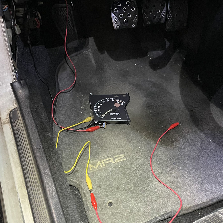
Yesterday I finally got a hold of another tach (wrecking yard parts) and tore my interior apart. My first thought is if the windings of the window motor and/or resistance from the headlights/blinkers are causing the tach to work, then I must have a faulty ground somewhere.

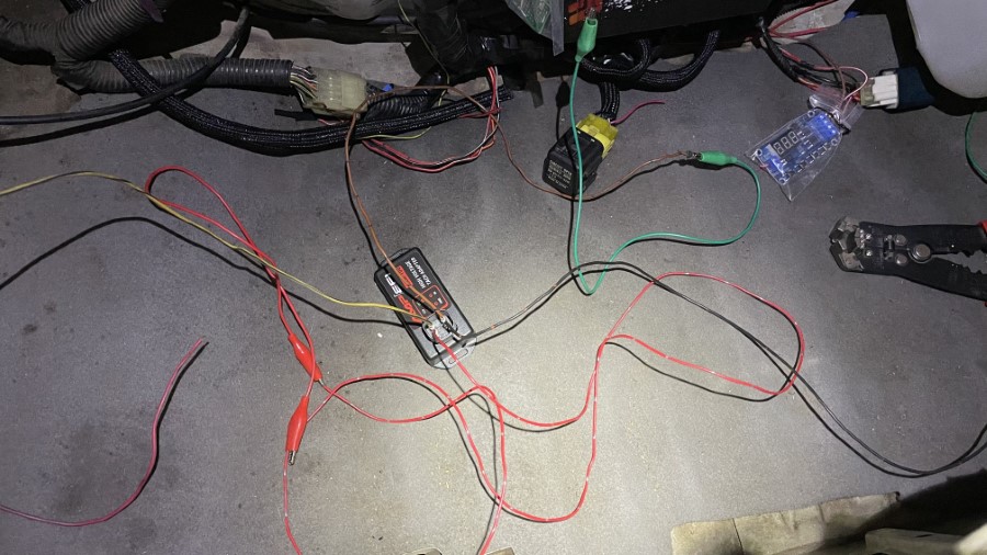
So I ran my own wires to the tach brain: A dedicated ignition ON +12v power to tach pin A, a dedicated ground to tach pin B, and a new single wire bypassing my chassis harness and straight from MS Options Pin #4 to the tach input pin C. When you cycle the ignition key to the ON position the tach bounces just like normal, but both cranking and idling the tach needle doesn't move, it just reads zero RPM. Then the moment you lay into the power window switch the tach instantly springs to life and reads perfectly steady RPM so long as you keep your finger on the window switch. Let go of the window switch, tach falls back to zero RPM.

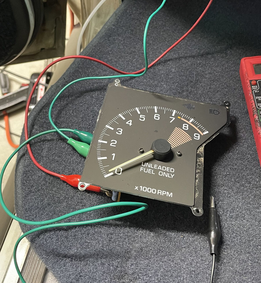
I then ran these three wires to the wrecking yard tach (shown below) and the very same thing happens: Twitches when first receiving power, then reads zero RPM with engine running, and instantly starts working when you operate a power window.


Testing
So then I was wondering if there is a jumper inside my MS that I'm supposed to use so I consulted the documentation and all I see for these PnP Gen2 models is that the options pin offers a square 0-12 v signal and to simply hook it up direct:
The Tach output pin of the option connector provides a 0-12 volt square-wave signal compatible with many factory and most aftermarket tachometers. Wire your tachometer's trigger wire to this pin.
I don't have a scope to properly read a square wave, but I probed my multimeter to MS Options Pin #4 Tach Output and with Key ON engine off it reads 12 volts. When the engine is idling (cold idle, ~1200 RPM) it reads 6.2 volts. When I rev it up to about 3K RPM the voltage doesn't change much or any at all. It was still about 6.2 or 6.3 volts.

Checking Vdd at the tach itself (pin A), I see ~12v with key ON and engine off, and 13.2v with engine running. So that's verified and it is a steady 13.2. (Also verified ground is a good ground.)

When you lay into the window switch, ie. the window is all the way down already but you hit the switch to lower the window, the voltage at the tach pin A drops to the high 9s, like 9.7 or 9.8v and the tach suddenly comes alive.

At this time, probing the MS Options Pin #4 Tach Output still reads 6.2 or 6.3v, it doesn't deflect when the window motor is jamming itself and the tach is working.

So it seems that when there is a greater voltage difference between tach +Vdd (pin A) and the Tach signal (tachometer pin C, aka MS Options Pin #4 "Tach Out") that the tach functions, but then again, this is a square wave so my voltmeter reading is probably useless info here...


Questions
So before I go through the process of opening up my MS to look at jumper options (which is a bit cumbersome to get to for how I have it all installed), I'd like to post up to ask...

1. Is there such a Jumper that I should enable for when I am using Coil On Plug (as not all jumpers are listed in the manual)?

2. Alternatively, is there some sort of circuitry I'm supposed to build to convert the 0-12v square wave to function with a late 1980s era Toyota EFI tachometer?


Thank you for the help!! Hopefully someone out there has encountered such an strange tach issue like this 🙏🏽

Regards,
BigMike

edit:
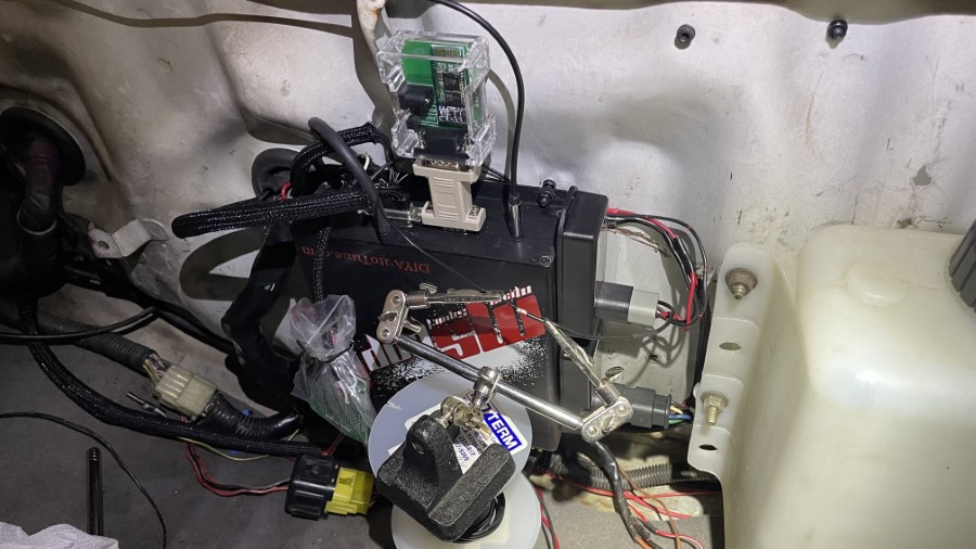
Here are my specific MS details:
  • MSPNP Gen2 from DYIAuto (intended for USDM Toyota MR2 1.6L 4A-GE platform) (product link)
  • Black board: "MSPNP2-T8590 V1.2 (2013)"
  • Main board: "MSPNP2 V1.3b"
  • MicroSquirt module: "V2.2M (2009)"
  • Firmware: MS2/Extra 3.4.4
  • TunerStudio: Ultra v3.1.08

Testing wrecking yard tach. Both the tach in my dash and testing this one here work great so long as there is some electrical or resistive load on the system
Image

My second wife 😍
Image
BigMike
MS/Extra Newbie
Posts: 21
Joined: Mon Jul 10, 2023 7:58 pm
Location: CenCal

Re: Help with Tach Output, strange tach behavior

Post by BigMike »

Just got home and playing some more with this. Also realizing that a square 0-12v signal is simply a low to high, or 0 to 12 repeating signal presumably with differing frequency based on spark firing speed.

Anyway, I tried adding a hefty resistor between the Vdd signal to the tach brain to drop that voltage down to about the same as what I read when laying into to the power window switch or about a 2.5v drop (via 470 k ohm) and still nothing.

I then added the same hefty resistor inline with the ground signal to the tach brain and still nothing.

This is so wild!

Here’s a quick n dirty cold start video of the situation
https://youtu.be/95RdRRk0eg0

Edit: trying to embed YT vid

[youtube]https://www.youtube.com/watch?v=95RdRRk0eg0[/youtube]

[youtube]https://youtu.be/95RdRRk0eg0[/youtube]
BigMike
MS/Extra Newbie
Posts: 21
Joined: Mon Jul 10, 2023 7:58 pm
Location: CenCal

Re: Help with Tach Output, strange tach behavior

Post by BigMike »

Had another thought...

The stock setup with one coil and one igniter has the tach output from the igniter possibly going high (or low) on every firing event which would be 4 times higher than COP, as now each coil only has to fire once per spark plug. (A major benefit of COP.)

So now I am wondering, what if the "Tach Output" Options pin #4 that MS is sending doesn't know that I'm running COP, then it would be sending a square wave signal that is 1/4th the frequency of what my tachometer is expecting?

To run Coil On Plug, I am using the four coil drivers out of the Options port (Pins 14,15,16,17 for Spark Outputs D,C,B,A, respectively). What if I tap four wires into these four outputs using diodes on each to prevent cross-talk, and then run that 4x combined signal to my tach input? Then my tach would see all combined coil events as if there was just one coil. According to the manual, these are 5v out signals, so I could use a fast switching simple transistor, like TIP120 or something, to send a clean 12v/high signal to the tach. So no coil firing, the tach receives 0v. If any of the four coils fire, then the tach receives 12v for a split second. Honestly, I have no clue how the "0-12v square wave signal" is formatted or what it looks like, I'm just thinking out loud over here :D


Of course this wouldn't have anything to do with the strange window and blinker phenomenon, also, this contradicts the fact that the tach reads correctly when it does work via the strange phenomenon, so the "tach out" signal probably is the correct frequency despite using COP...

I poked around some in TunerStudio and didn't see a setting for Tach Out vs Single or Wasted Spark or COP... Does anyone know if the Options port "Tach Output" pin can be reconfigured via TunerStudio? I will take apart everything to get to the MS and look inside at the jumpers, seems this would be a jumper setting as I asked about in my opening post.


Thanks
BigMike
prof315
Super MS/Extra'er
Posts: 3790
Joined: Sun Jan 18, 2009 3:13 am
Location: Melbourne, FL

Re: Help with Tach Output, strange tach behavior

Post by prof315 »

If I remember correctly, Tach Out on PnPs is a dedicated circuit and the standard output is 1 pulse per cylinder no matter what the coil configuration is.
Linfert Performance/321 Motorsports
SCCA 2019 SM National Champion Crew Chief
SCCA 2023 FP National Champion Tuner/electrical engineer
100s of MS systems built installed and tuned
Support the developers!
BigMike
MS/Extra Newbie
Posts: 21
Joined: Mon Jul 10, 2023 7:58 pm
Location: CenCal

Re: Help with Tach Output, strange tach behavior

Post by BigMike »

prof315 wrote: Tue Mar 05, 2024 1:26 pm If I remember correctly, Tach Out on PnPs is a dedicated circuit and the standard output is 1 pulse per cylinder no matter what the coil configuration is.
Thank you very much for the reply. This makes sense because the reading is accurate when it works. 👍🏼

Does anyone out there know or can test what voltage comes out of the stock 1980s era Toyota EFI igniter for the stock tach? Maybe the stock igniter single doesn’t output a 12v square wave, but maybe only 9 or 6v?

(Such that maybe by placing a load on the electrical system — ie. window motor loading up — drops the voltage into a range the stock tach is happy with?)

Thanks
BigMike
bobxyz
Helpful MS/Extra'er
Posts: 117
Joined: Tue May 23, 2023 4:30 pm

Re: Help with Tach Output, strange tach behavior

Post by bobxyz »

When you say the tach wiring has "a single black wire (pin C) connected to the stock igniter" what pin on the igniter is used?

If it's the igniter-to-coil output wire, then the tach is probably expecting a high-voltage flyback pulse (briefly reaching 30+ volts). For this, you need to build or buy an adapter - see http://www.msextra.com/doc/ms1extra/MS_ ... m#tachoout or https://www.diyautotune.com/product/axm ... h-adapter/

If the tach is connected to the ecu-to-igniter input wire, or a dedicated igniter pin for only the tach, then I don't know what's causing the problem.
BigMike
MS/Extra Newbie
Posts: 21
Joined: Mon Jul 10, 2023 7:58 pm
Location: CenCal

Re: Help with Tach Output, strange tach behavior

Post by BigMike »

Ohh man this has gotta be it, thank you for the tip, I couldn’t order that AXM-100 fast enough! I’ve already spent far more messing around with this 🤣

Will update the thread once it’s installed 👍🏼

I put the car back together and took it out for some late night idle tuning (few weeks in on learning PID), and here is what it looks like with the blinkers:

https://youtu.be/tK-7ylGf2QI

Good times

BigMike
BigMike
MS/Extra Newbie
Posts: 21
Joined: Mon Jul 10, 2023 7:58 pm
Location: CenCal

Re: Help with Tach Output, strange tach behavior

Post by BigMike »

Also, sorry, was too excited to order the part and didn’t answer your Q! 🤦🏽‍♂️

On my setup, the stock igniter has I think 6 wires:
— Two run to the ECU
— Two connect to the single stock coil (+Vdd & -Vcc)
— One is ignition ON +Vdd
— And one is the black wire that runs to the tach

I’ve read where some tachs run off of the coil but for me it runs off the igniter. (Could be the same signal)

So without my stock igniter I have no tach output signal. Stock ECU does not drive the tach

Now that I’m thinking all this, when I was researching the sequential COP setup last year I remember seeing a guy who went COP on a normally aspirated 4A-GE + MegaSquirt where he kept the stock igniter plugged in somehow but only just to provide the tach output. I still have my igniter and I’m sure I could figure this out on my own but meh… I don’t like it (also it’s a very rare Supercharged type that I can sell for triple the AXM 👍🏼) (Or this will be Plan B 😅)

Regards
BigMike
bobxyz
Helpful MS/Extra'er
Posts: 117
Joined: Tue May 23, 2023 4:30 pm

Re: Help with Tach Output, strange tach behavior

Post by bobxyz »

Since there is a separate wire from the igniter to the tach, versus the coil - wire also going to the tach, I'd guess that the tach expects a simple 12v square wave and does NOT need a higher voltage. Adding a voltage booster might even damage the tach.

I read the tread in more detail and a couple things stand out.

You wrote:
When you lay into the window switch, ie. the window is all the way down already but you hit the switch to lower the window, the voltage at the tach pin A drops to the high 9s, like 9.7 or 9.8v and the tach suddenly comes alive.
This is bad. The +12v at the tach (pin A) should NOT drop at all, or maybe only a small fraction of a volt, when other accessories are used. Most likely, there's a poor/corroded +12v connection somewhere upstream of the cluster and the window relays. When you use the windows, does the dashboard voltage gauge drop?

prof315 wrote:
If I remember correctly, Tach Out on PnPs is a dedicated circuit
This may be a clue to the problem. I'd contact DIYautotune and ask them specifically about the Tach Out circuit when using their 4A-GE PNP box with a 4A-GE harness but a 4A-GZE engine and the 24/2 dizzy CAS. It might just need something simple like a pullup resistor.
BigMike
MS/Extra Newbie
Posts: 21
Joined: Mon Jul 10, 2023 7:58 pm
Location: CenCal

Re: Help with Tach Output, strange tach behavior

Post by BigMike »

Update! Got it fixed!

!Solved

Thank you bobxyz for the tip on the AXM-100, it was exactly what was needed!

I did see your caution regarding damaging the tach, but figured I would not cancel the order and wait for it to arrive and do some testing prior to hooking everything up in case I needed to return the device.

The device finally arrived and yesterday evening I had time to give it a shot. Loosely wired it in and checked voltage while cranking prior to connecting it to my test/wrecking yard tach, and all I ever saw on a regular digital volt meter was a peak of 12 volts. I then decided to connect it to the wrecking yard tach and sure enough I had the needle bouncing while cranking (pedal at WOT for no fuel/crank only), and then after deciding to fire it up, it worked perfectly.

Picked up all the test leads and installed it into the car and wa-la, tach works!! Drove it to work this morning, so nice having the tach working, first time since November :yeah!:

Image

Image

Image

My Toyota 4A-GZE Coil On Plug setup now has the AXM-100 to drive the stock Tach (shown above mounted to the MegaSquirt at top-right) (which is not needed for normal factory single coil + igniter setups) and AXM-120 for the individually grounded "NE" VR sensor from the 24/2 Supercharged CAS (lower-right) (the "G2" VR sensor circuit is controlled via the single built-in MegaSquirt VR filter) (the non-Supercharged 4/1 CAS setup only requires one VR filter, which this PnP MegaSquirt includes built-in, but a second VR filter is needed for the Supercharged 24/2 CAS setup) ("G1" VR sensor circuit is not used)


Here is a video of it in action finally! WOOT!

https://youtu.be/e6EhY2VZl7o

Regards,
BigMike
bobxyz
Helpful MS/Extra'er
Posts: 117
Joined: Tue May 23, 2023 4:30 pm

Re: Help with Tach Output, strange tach behavior

Post by bobxyz »

Glad it's working and that you had a spare tach to try it out on first.

I tried searching for a better description of the original VAST N tach signal, but couldn't find much. It must pre-date the internet. The mid 1980s is about when tachometers were switching over from being driven directly by the coil primary (using the high voltage flyback pulse) to being driven by the ECU (using a 12v pulse), so apparently your setup is expecting the high voltage pulse.
Post Reply