I added a new page to the manual with some info about physical flowing of injectors to determine dead time. I also plotted out the non-linear region on two injectors. I found them oddly similar but not what I was expecting at all.
http://www.msextra.com/doc/ms3/injdeadtime.html
There's also a video (12 mins) of the testing http://www.youtube.com/watch?v=lJgi8l-2XG4
The spreadsheet is available from the manual page.
hope that's all of interest
James
Injector dead time and non-linear + video
Moderators: jsmcortina, muythaibxr
-
jsmcortina
- Site Admin
- Posts: 39614
- Joined: Mon May 03, 2004 1:34 am
- Location: Birmingham, UK
- Contact:
Injector dead time and non-linear + video
I can repair or upgrade Megasquirts in UK. http://www.jamesmurrayengineering.co.uk
My Success story: http://www.msextra.com/forums/viewtopic ... 04&t=34277
MSEXTRA documentation at: http://www.msextra.com/doc/index.html
New users, please read the "Forum Help Page".
My Success story: http://www.msextra.com/forums/viewtopic ... 04&t=34277
MSEXTRA documentation at: http://www.msextra.com/doc/index.html
New users, please read the "Forum Help Page".
Re: Injector dead time and non-linear + video
Thank you James 
Re: Injector dead time and non-linear + video
Subscribed =)

-
racingmini_mtl
- Super MS/Extra'er
- Posts: 9130
- Joined: Sun May 02, 2004 6:51 am
- Location: Quebec, Canada
- Contact:
Re: Injector dead time and non-linear + video
One thing that should be mentioned is that the test should be done with the same injector drivers as the ones that will be used on the engine or at least the same driver type. Each driver type will have its own electrical characteristics which will have some influence on dead time.
So if you're going to use MS3X drivers, V3.0 drivers, external peak&hold drivers or some other drivers, use these for testing. And since the difference in dead time value will be dependent on the driver and the injector, it is not possible to tell what the difference will (or even say if there will be one) without performing the test for a specific combination.
Jean
-
jsmcortina
- Site Admin
- Posts: 39614
- Joined: Mon May 03, 2004 1:34 am
- Location: Birmingham, UK
- Contact:
Re: Injector dead time and non-linear + video
A very valid point. (Good thing I already mentioned it in the manual !)
James
James
I can repair or upgrade Megasquirts in UK. http://www.jamesmurrayengineering.co.uk
My Success story: http://www.msextra.com/forums/viewtopic ... 04&t=34277
MSEXTRA documentation at: http://www.msextra.com/doc/index.html
New users, please read the "Forum Help Page".
My Success story: http://www.msextra.com/forums/viewtopic ... 04&t=34277
MSEXTRA documentation at: http://www.msextra.com/doc/index.html
New users, please read the "Forum Help Page".
Re: Injector dead time and non-linear + video
Here's a method that's worked on car:
Rx7 550cc injectors

Yellow RX-8 injectors @ 13.2 volts
Rx7 460cc injectors at ~13.5vIdle car while datalogging, and have a means of changing injector electrical pulse width slowly up and down while logging. Car must have a reasonably stable idle at a fairly fixed RPM, and battery voltage must be constant throughout.
Log MAP, AFR, Battery volts, and Injector electrical pulse width, while idling. Slowly raise and lower injector on time (I did it by changing the AEM's injector dead time vs. battery voltage, across 3 cells, straddling the battery voltage that I was seeing). Slowly raise and lower it until the RPM starts to drop significantly or the car starts to misfire. I could go from 11:1 to 16.3:1 or so and back. Do this several times, it may take you a few minutes.
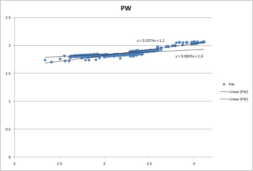
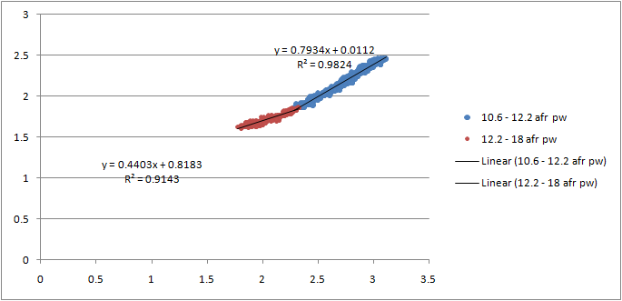
Then examine the datalogs. Do an XY plot. Plot MAP divider AFR on the X-axis, then injector on-time on the Y-axis. You can use AEMLog for this, or MS Excel. Excel has the advantage of having a linear curve fit ("trendline, linear"). The datapoints should form a line. If you project this line to the Y-axis, the intercept is the dead time. See attached.
In Excel, do a scatter plot, then add a trendline. Select "linear", and in the options, select "show equation". If your data is clean and has little noise, the Y-intercept will show in the equation. If not, select "Set Intercept", and try different values until the trendline appears to describe the quiet part of the data. In my example, it's 930 us. This is for a friend's 750cc RC hi-impedance injectors. Note that on the bottom left of the data, there appears to be an arrowhead shape. This is noise in the data, due to lean misfire, at narrow injector duty cycles / leanness.
Rx7 550cc injectors
Yellow RX-8 injectors @ 13.2 volts
1991 Boosted Miata Running MS3 + MSX w/Full Seq.
https://www.trubokitty.com
https://www.trubokitty.com
-
jsmcortina
- Site Admin
- Posts: 39614
- Joined: Mon May 03, 2004 1:34 am
- Location: Birmingham, UK
- Contact:
Re: Injector dead time and non-linear + video
That's a very small set of pulsewidths - is that representative of your operating range?
James
James
I can repair or upgrade Megasquirts in UK. http://www.jamesmurrayengineering.co.uk
My Success story: http://www.msextra.com/forums/viewtopic ... 04&t=34277
MSEXTRA documentation at: http://www.msextra.com/doc/index.html
New users, please read the "Forum Help Page".
My Success story: http://www.msextra.com/forums/viewtopic ... 04&t=34277
MSEXTRA documentation at: http://www.msextra.com/doc/index.html
New users, please read the "Forum Help Page".
Re: Injector dead time and non-linear + video
Very nice James! One thing I have noticed in working with deadtimes is that the voltage correction curve is the most important thing to get right. You can be off on the deadtime @13.2 by + or - .2 or .3 ms and things will remain stable and smooth IF the correction curve is right.
Linfert Performance/321 Motorsports
SCCA 2019 SM National Champion Crew Chief
SCCA 2023 FP National Champion Tuner/electrical engineer
100s of MS systems built installed and tuned
Support the developers!
SCCA 2019 SM National Champion Crew Chief
SCCA 2023 FP National Champion Tuner/electrical engineer
100s of MS systems built installed and tuned
Support the developers!
Re: Injector dead time and non-linear + video
I'm using the same Siemens deka 630's with Jean's P&H board. (I know P&H not needed with high Z injectorsracingmini_mtl wrote:One thing that should be mentioned is that the test should be done with the same injector drivers as the ones that will be used on the engine or at least the same driver type. Each driver type will have its own electrical characteristics which will have some influence on dead time.
So if you're going to use MS3X drivers, V3.0 drivers, external peak&hold drivers or some other drivers, use these for testing. And since the difference in dead time value will be dependent on the driver and the injector, it is not possible to tell what the difference will (or even say if there will be one) without performing the test for a specific combination.
Jean
I just accuired a measurement glass and if a have time on the weekend I was planning to do the same test as James so we would get some info how much the injector driver circuit affects the dead time.
I will report back when I get the test ready.
-
ragepower
- Experienced MS/Extra'er
- Posts: 280
- Joined: Fri Dec 17, 2010 9:13 am
- Location: Leiria - Portugal
Re: Injector dead time and non-linear + video
Question: In the overall injector flow measurement, I couldn't understand how is the injector control, seams to me that you said something like full duty cycle, to not do calculations with dead time.
You use a 12V DC supply in continuous to open the injector, right? This will not overheat the injector?
You use a 12V DC supply in continuous to open the injector, right? This will not overheat the injector?
-
jsmcortina
- Site Admin
- Posts: 39614
- Joined: Mon May 03, 2004 1:34 am
- Location: Birmingham, UK
- Contact:
Re: Injector dead time and non-linear + video
I retained the 3R3 resistor in series.ragepower wrote:You use a 12V DC supply in continuous to open the injector, right? This will not overheat the injector?
In the spreadsheets I posted you can see the flow calculated from the more precise measurements too.
James
I can repair or upgrade Megasquirts in UK. http://www.jamesmurrayengineering.co.uk
My Success story: http://www.msextra.com/forums/viewtopic ... 04&t=34277
MSEXTRA documentation at: http://www.msextra.com/doc/index.html
New users, please read the "Forum Help Page".
My Success story: http://www.msextra.com/forums/viewtopic ... 04&t=34277
MSEXTRA documentation at: http://www.msextra.com/doc/index.html
New users, please read the "Forum Help Page".
Re: Injector dead time and non-linear + video
I did this for the yellow RX8 injectors only to get really long dead times! In practice most are using about half of what I got. I am starting to think I was sold some cheap Chinese copy instead of the real thing. Then again, as reference I got 2.85ms@12.7V for stock Miata 1.8 BP engine 265cc/min injectors.

I also measured small pulse response. There seems to be a characteristic hump in the output right at the shortest pulses. Same at all voltages.

The two curves in the middle (blue and what is that, brown..)would obviously need more measument points to get their hump in line with the outer ones.
As you can see, at under ~3.5ms the injector is not flowing at all !!!
I even verified with a scope that MS was acually outputting what I was asking. Though I must admit my scope is an old piece of junk...
-
jsmcortina
- Site Admin
- Posts: 39614
- Joined: Mon May 03, 2004 1:34 am
- Location: Birmingham, UK
- Contact:
Re: Injector dead time and non-linear + video
Very interesting indeed. I was not expecting that 'hump' so it is good to see someone else repeating it too. It also means that we MUST avoid that area or it will be impossible to tune and corrections will work backwards etc.
How are you driving these injectors electrically ? Seems something might be amiss to get such huge dead times.
James
How are you driving these injectors electrically ? Seems something might be amiss to get such huge dead times.
James
I can repair or upgrade Megasquirts in UK. http://www.jamesmurrayengineering.co.uk
My Success story: http://www.msextra.com/forums/viewtopic ... 04&t=34277
MSEXTRA documentation at: http://www.msextra.com/doc/index.html
New users, please read the "Forum Help Page".
My Success story: http://www.msextra.com/forums/viewtopic ... 04&t=34277
MSEXTRA documentation at: http://www.msextra.com/doc/index.html
New users, please read the "Forum Help Page".
Re: Injector dead time and non-linear + video
Outputs through the expander and I think I connected all grounds (I'll need to check that from my photos). Wires were about 1.5m long 0.75mm^2 to and from the injectors. I used a variable voltage source and also tried straight from the car battery with quite thick wire to make sure the long deadtimes were not caused by my source sagging. Not much of difference between them. I extrapolated the deadtimes from several pulses between 10 and 75 ms where the injectors operated very linearly. Channels A to D connected to their injectors were all putting out similar dead times so it's not like a driver is malfunctioning.
Re: Injector dead time and non-linear + video
This thread has been focusing on the inertia and physical opening and closing time of the injector. I think that 'hump' is an effect of the inertia and physical flow restrictions of the fuel and the regulator. When the pintle opens, the inertia of the fuel prevents it from flowing as fast as the rapidly-opening orifice will allow. As the fuel begins to flow, the pressure drops off and so does the flow; once the regulator responds to the demand, the pressure goes back up as does the flow.
It would be very interesting to see the effect of small surge reservoirs / accumulators just upstream of the injectors. I would submit that the linearity at small openings would be greatly improved. We might be approaching diminishing returns as regards complexity , but it might help with over-sized injectors at idle.
It would be very interesting to see the effect of small surge reservoirs / accumulators just upstream of the injectors. I would submit that the linearity at small openings would be greatly improved. We might be approaching diminishing returns as regards complexity , but it might help with over-sized injectors at idle.
Temporarily shut down - back soon!
QuadraMAP Sensor Module -- PWM-to-Stepper Controller -- Dual Coil Driver
Coming soon: OctoMAP Sensor Module
TTR Ignition Systems
QuadraMAP Sensor Module -- PWM-to-Stepper Controller -- Dual Coil Driver
Coming soon: OctoMAP Sensor Module
TTR Ignition Systems
-
Matt Cramer
- Super MS/Extra'er
- Posts: 17507
- Joined: Thu Apr 16, 2009 8:08 pm
Re: Injector dead time and non-linear + video
One other safety tip I'd like to add. There are a couple of test fluids that you can use that are close to the viscosity of gasoline but don't vaporize or burn as well. Stoddard solvent or Safety-Kleen can make good cheap injector test fluids that are less dangerous than using gasoline.
Matt Cramer -1966 Dodge Dart slant six running on MS3X
Re: Injector dead time and non-linear + video
I don't quite follow that logig. For example if you look at the green curve (14.5V), at ~4.2ms I have gotten ~0.003 grams of fuel out of the injector. Even if I had a pressure drop after this moment the injector will not suck part of it back as the curve suggests! Surely I would still get more fuel out with, say, a 4.5ms pulse - however I am not, but much less.dontz125 wrote:I think that 'hump' is an effect of the inertia and physical flow restrictions of the fuel and the regulator. When the pintle opens, the inertia of the fuel prevents it from flowing as fast as the rapidly-opening orifice will allow. As the fuel begins to flow, the pressure drops off and so does the flow; once the regulator responds to the demand, the pressure goes back up as does the flow.
Thus it must rather have to do with the inertia of the injector itself. Here is how I like to think of it:
A short pulse will ´kick´ the injector needle up, it will then decelerate gradually while still opening more (inertia), then reverse its direction and accelerate back to its seat. Like this we get a fairly long open time as time is used in gradual accelerations. A longer pulse will quickly force the needle up to its stop, possibly even causing rebound back towards the seat. If current is cut at this point the needle will return fairly quickly to its seat, thus a shorter open time with a longer electrical pulse!
Make any sense..?
Re: Injector dead time and non-linear + video
This is a quite good explanation of this effect.j-po wrote: Thus it must rather have to do with the inertia of the injector itself. Here is how I like to think of it:
A short pulse will ´kick´ the injector needle up, it will then decelerate gradually while still opening more (inertia), then reverse its direction and accelerate back to its seat. Like this we get a fairly long open time as time is used in gradual accelerations. A longer pulse will quickly force the needle up to its stop, possibly even causing rebound back towards the seat. If current is cut at this point the needle will return fairly quickly to its seat, thus a shorter open time with a longer electrical pulse!
If the flow restrictions and pressure changes causes this, then it happen every injectors, but with good injector these curves (hump) are really small. Look example this ID1000 curves.
And this is a really good reason to buy "best possible" injectors (this time Bosch EV14).
j-po: This You measured DeadTime looks wery weird, are You sure, that there is nothing error? I don't ever seen this big DT values.
Here are some example of curves what I measured.
Last edited by jalai on Sun Feb 02, 2020 1:28 am, edited 1 time in total.
-
jsmcortina
- Site Admin
- Posts: 39614
- Joined: Mon May 03, 2004 1:34 am
- Location: Birmingham, UK
- Contact:
Re: Injector dead time and non-linear + video
Lots of really interesting data in your photo album!
Do you have it collected together with explanatory text as a webpage of PDF ?
James
Do you have it collected together with explanatory text as a webpage of PDF ?
James
I can repair or upgrade Megasquirts in UK. http://www.jamesmurrayengineering.co.uk
My Success story: http://www.msextra.com/forums/viewtopic ... 04&t=34277
MSEXTRA documentation at: http://www.msextra.com/doc/index.html
New users, please read the "Forum Help Page".
My Success story: http://www.msextra.com/forums/viewtopic ... 04&t=34277
MSEXTRA documentation at: http://www.msextra.com/doc/index.html
New users, please read the "Forum Help Page".
Re: Injector dead time and non-linear + video
Hei Jari,jalai wrote: j-po: This You measured DeadTime looks wery weird, are You sure, that there is nothing error? I don't ever seen this big DT values.
Problem is I am pretty confident I setup everything correctly and on the other hand I realize the results suggest something is amiss. I used the only fuel rail I have - from my car and it is pretty difficult to get off so I don't feel like replicating the tests right away.
Thanks for your reference data. In comparison the RX8 injectors sure seem to have a considerable nonlinearity to them even if you disregard the weird dead time.