Hi,
I have a MS3 with expansion board MS3X. I also have a Mustang 91 with T5 transmission and would like to use traction control feature. Could I use stock VSS sensor for "driven wheel" or accuracy is not good? For undriven wheel (Front), I was thinking about mounting hall sensor that will pickup brake rotor vanes. Witch sensor could I use and input should I use? I read PT4, datalog in but not quite use about input voltage and what is need to be accurate.
Thanks for helping me out guys,
Martin
Help with traction control wiring and needs
Moderators: jsmcortina, muythaibxr
Re: Help with traction control wiring and needs
I'm using the stock sensor off of my T5 into a VR conditioner like the JBPerf board, accuracy is great.

Re: Help with traction control wiring and needs
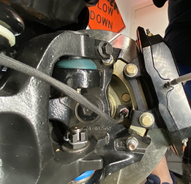
As mentioned the VSS should be fine for the driven wheel. For the undriven wheel I would trigger off the heads of the studs. That's how mine is set up and it works just fine. And the sensor is tucked behind the rotor out of harms way.
2004 Cobra, MS3PNP, flex fuel, knock sensor, Whipple, etc.
AKA: 01yellerCobra
AKA: 01yellerCobra
Re: Help with traction control wiring and needs
It is possible to use stock VSS without conditioner or I could use same hall sensor as undriven wheel?
Witch sensor are you using and on witch input you wired yhem?
Thanks guys
Witch sensor are you using and on witch input you wired yhem?
Thanks guys
Re: Help with traction control wiring and needs
Pt4 (pin 31 on MS3X) is set aside for high frequency digital input which is what most use to take in a stock type VSS signal. For lower frequency inputs (like reading off the wheel studs) you can use an input like pin 28 (Tableswitch In) on the MS3X. At least that is what I am doing. As far as sensors go I really like the Cherry hall sensors, they are robust and tried and true.
Front wheel
Rear wheel
Front wheel
Rear wheel
1995 Ford Lightning. Dart based 427 Windsor, Novi 2000, full sequential, E-85, etc. MS3X/v3.57
http://www.buildpics.org/
http://www.buildpics.org/
Re: Help with traction control wiring and needs
Hi Raymond, because you are using Hall Sensor GS100502, front is connected to Tableswitch in and is rear could be connected to PT4 than? I'm not sure if my stock VSS is hall sensor or VR sensor? I've look at digikey for cherry sensor and they look BO. What about your trigger wheel on your DS, what part is that? Interesting...Raymond_B wrote:Pt4 (pin 31 on MS3X) is set aside for high frequency digital input which is what most use to take in a stock type VSS signal. For lower frequency inputs (like reading off the wheel studs) you can use an input like pin 28 (Tableswitch In) on the MS3X. At least that is what I am doing. As far as sensors go I really like the Cherry hall sensors, they are robust and tried and true.
Thanks
Last edited by martroy on Fri Jul 09, 2021 8:52 pm, edited 1 time in total.
Re: Help with traction control wiring and needs
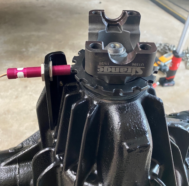
The PT4 input can handle high frequency inputs whereas an input like Tableswitch is for the lower frequency. Before I changed the rear sensor I was using the stock Ford truck 8.8" tone ring that had 108 teeth. That high tooth count required PT4, but as you see the new setup has 16 teeth which I think is right about the limit of what the low freq inputs can take, but that depends on driveshaft RPM so I am going to continue to use PT4 for the rear.
Not sure of the part# you posted, but I've been using GS100102 or GS100202. One is stainless the other is the red one most see. The stainless one is nice and I use it for my crank sensor, these two red ones I had extra so I'll use them for now.
The setup for the 8.8" pinion yoke sensor came from Motion Raceworks https://www.motionraceworks.com/product ... olt-dana60 Or you can piece your own together using Strange components.
1995 Ford Lightning. Dart based 427 Windsor, Novi 2000, full sequential, E-85, etc. MS3X/v3.57
http://www.buildpics.org/
http://www.buildpics.org/
Re: Help with traction control wiring and needs
Taking notes of input to use, thanks. Those hall sensors are 3 wires and connected 12v, ground and signal return directly into MS input without resistor, diode or cap?Raymond_B wrote:Not sure of the part# you posted, but I've been using GS100102 or GS100202. One is stainless the other is the red one most see. The stainless one is nice and I use it for my crank sensor, these two red ones I had extra so I'll use them for now.
The setup for the 8.8" pinion yoke sensor came from Motion Raceworks https://www.motionraceworks.com/product ... olt-dana60 Or you can piece your own together using Strange components.
That will be a fall/winter project and report back one installed.
Re: Help with traction control wiring and needs
The sensors need a pullup resistor, I run a 12v supply Cherry recommends a 2.4k pullup.martroy wrote:Taking notes of input to use, thanks. Those hall sensors are 3 wires and connected 12v, ground and signal return directly into MS input without resistor, diode or cap?Raymond_B wrote:Not sure of the part# you posted, but I've been using GS100102 or GS100202. One is stainless the other is the red one most see. The stainless one is nice and I use it for my crank sensor, these two red ones I had extra so I'll use them for now.
The setup for the 8.8" pinion yoke sensor came from Motion Raceworks https://www.motionraceworks.com/product ... olt-dana60 Or you can piece your own together using Strange components.
That will be a fall/winter project and report back one installed.
1995 Ford Lightning. Dart based 427 Windsor, Novi 2000, full sequential, E-85, etc. MS3X/v3.57
http://www.buildpics.org/
http://www.buildpics.org/
Re: Help with traction control wiring and needs
Thank you Raymond.
Re: Help with traction control wiring and needs
You run independent 12v supply or feeded from the battery? With alternator, it will be around 14-14,5v?
Because its 12v on input on MS, it wont break anything cause its internally protected?
Thanks
Because its 12v on input on MS, it wont break anything cause its internally protected?
Thanks
Re: Help with traction control wiring and needs
You're welcome, no problem!martroy wrote:You run independent 12v supply or feeded from the battery? With alternator, it will be around 14-14,5v?
Because its 12v on input on MS, it wont break anything cause its internally protected?
Thanks
When I planned my harness I put in a few +12V circuits for supplying things like IAC, sensors, injectors, etc. Those are all on relays so they do not energize until key on and power is fused from the battery.
1995 Ford Lightning. Dart based 427 Windsor, Novi 2000, full sequential, E-85, etc. MS3X/v3.57
http://www.buildpics.org/
http://www.buildpics.org/
Re: Help with traction control wiring and needs
Understood, so it doesnt matter if cherry sensor doesnt have a "regulated supplied voltage" than? On the MS side, only a pull-up resistor in the harness and directly into the input of my choice (Datalog in, PT4, Launch in) ?Raymond_B wrote:When I planned my harness I put in a few +12V circuits for supplying things like IAC, sensors, injectors, etc. Those are all on relays so they do not energize until key on and power is fused from the battery.
In the MS documentation, it was saying input expect to receive a 0-5V signal ???
Re: Help with traction control wiring and needs
I do not believe so no, mine are working fine with 12v.martroy wrote:Understood, so it doesnt matter if cherry sensor doesnt have a "regulated supplied voltage" than? On the MS side, only a pull-up resistor in the harness and directly into the input of my choice (Datalog in, PT4, Launch in) ?Raymond_B wrote:When I planned my harness I put in a few +12V circuits for supplying things like IAC, sensors, injectors, etc. Those are all on relays so they do not energize until key on and power is fused from the battery.
In the MS documentation, it was saying input expect to receive a 0-5V signal ???
You can run 5V if you wish, just use the appropriate pull up.
1995 Ford Lightning. Dart based 427 Windsor, Novi 2000, full sequential, E-85, etc. MS3X/v3.57
http://www.buildpics.org/
http://www.buildpics.org/
Re: Help with traction control wiring and needs
Finally, I've started slowly that project and here's my finding.
I've built a 16 tooth wheel that will fit on the rear end like yours. To experiment sensor, resistor and speed, I've installed the tooth wheel on my press drill. When using PT4 input, I could get 99-100 KPH. When I use DatalogIn or Tableswitch, at 69,1, it goes down to 5,8 KPH for few seconds and getting up after.
Is there something else I need to configure / set it up?
Thanks guys.
Re: Help with traction control wiring and needs
You need to figure at what RPM you are spinning that wheel and then calculate the frequency generated. Then try to calculate what the vehicle will generate. For my truck I was calculating driveshaft RPM based on my max MPH.martroy wrote:Finally, I've started slowly that project and here's my finding.
I've built a 16 tooth wheel that will fit on the rear end like yours. To experiment sensor, resistor and speed, I've installed the tooth wheel on my press drill. When using PT4 input, I could get 99-100 KPH. When I use DatalogIn or Tableswitch, at 69,1, it goes down to 5,8 KPH for few seconds and getting up after.
Is there something else I need to configure / set it up?
Thanks guys.
1995 Ford Lightning. Dart based 427 Windsor, Novi 2000, full sequential, E-85, etc. MS3X/v3.57
http://www.buildpics.org/
http://www.buildpics.org/
Re: Help with traction control wiring and needs
Understood but that is very "slow" cause I have a 4.10 rear gear and 100 KPH (60 MPH) is not that fast. I've tested with wheel stud (4 bolt) and now, it's "working" but not much accurate/responsive as 16 teeth wheel.
Re: Help with traction control wiring and needs
Yeah, it is what it is. I am personally going to use my high resolution for my main VSS and then just front wheel 5 lug stud "low" resolution for traction control input. Others have done it and it seems to have worked no problem. If it becomes an issue then the Microsquirt flashed as an IO box is an alternative.martroy wrote:Understood but that is very "slow" cause I have a 4.10 rear gear and 100 KPH (60 MPH) is not that fast. I've tested with wheel stud (4 bolt) and now, it's "working" but not much accurate/responsive as 16 teeth wheel.
1995 Ford Lightning. Dart based 427 Windsor, Novi 2000, full sequential, E-85, etc. MS3X/v3.57
http://www.buildpics.org/
http://www.buildpics.org/
Re: Help with traction control wiring and needs
Wondering if I could use Flex input on Ms3x board directly because I've read somewhere its a high frequency one???
Wondering too why in manuals, they are saying PT4 as a 0-5v input and with cherry sensor, they are working at 12v if I'm right? Dont want to damage anything there.
Thanks
Wondering too why in manuals, they are saying PT4 as a 0-5v input and with cherry sensor, they are working at 12v if I'm right? Dont want to damage anything there.
Thanks
Re: Help with traction control wiring and needs
Will Flex input with 12v pullup will work for high frequency VSS?
Thanks
Thanks