Hello all,
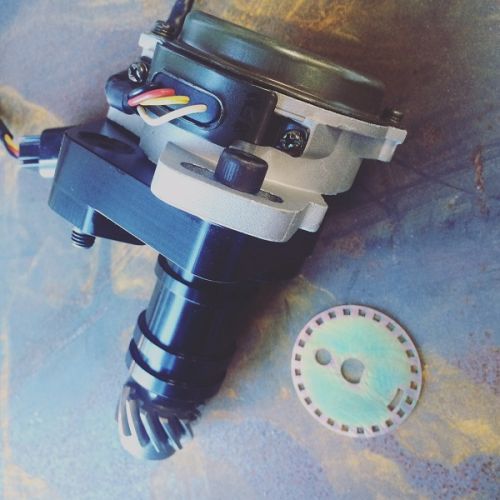
I'm still a newbie to megasquirt. Currently preparing my MS2/Extra 3.4.x / 3.57 PCB board to handle this DSM CAS using Yoshifab's 24/1 trigger disk:
I've been reading the manual and other forum posts for several months now and believe that I've finally stitched together the relevant instructions that are spread throughout the manual.
Relevant sections from the manual (Dated 2016-02-02):
5.2 Crank and Cam tach inputs
Installs requiring a second tach input (cam sensor or part of a CAS) will require additional internal modifications.
See section 5.2.14
5.2.3 Hall sensor input
There are two main categories of hall sensor
- open-collector (needs a pull-up resistor)
- built-in pull-up resistor (covered in section 5.2.4)
VR Input with pullup for hall sensors, LS2/58X, optical sensors or points
- Find JP1 in the bottom right of the board. Place a jumper across positions 1 and 2
- Find J1 in the middle of the board. Place a jumper across positions 3 and 4
- Install a 1k resistor (any value 470R - 2k2 is likely ok) onto the pads marked R57
- With a small screwdriver, turn the pots, R52 and R56, 7 turns anticlockwise (sometimes you may feel a "click" when the end position is reached, they can't be damaged by turning too far.) and then turn R56 back about 2 turns clockwise.
R56 to get around 2.5V on your meter.
5.2.13 Mitsubishi CAS with aftermarket disc
When this kind of replacement trigger disc is installed the "Toothed Wheel" mode needs to be used - see section 6.9
5.2.14.2 Adding a cam sensor input - hall sensor / optical sensor
This option uses the spare opto-isolator on the mainboard for the cam input and matches the polarity inversion of the VR/universal tach input. This section is for open-collector sensors as covered in 5.2.3 that ground switch only.
- JP1/pin3 should be connected with a jumper wire to a spare pin on the main DB37 connector (e.g. SPR3)
- Connect J1/pin1 with a jumper wire to JS10 (ensuring that nothing else is connected.)
- Jumper XG1 - XG2
- Check that R12 is a 390R to 470R resistor, replace if not.
- Solder wires onto a 470R 1/4W resistor and cover in heat-shrink.
- Connect one wire to +5V
- Connect the other wire to JP1/pin3 (joining the jumper wire there.)
- Ensure that C30 is not fitted.
Various spark outputs (single coil, wasted spark, coil-on-plug) are supported by Toothed Wheel, the table in
section 6.9.1 shows possible options. See section 5.3 for ignitor, coil and wiring examples.
6.9.1 Wheel combinations
| Main Wheel | Secondary Wheel | Trigger wheel arrangement | Main wheel speed | 2nd trig every rotation of |
| Non-missing tooth on crank | Single tooth on cam | Dual wheel | Crank | Cam |
6.9.3 Wheel naming
24/1. This means 24 teeth (non-missing) on one wheel and a single tooth on a second wheel.
6.9.13 Mitsubishi CAS with aftermarket disc - coil-on-plug
With the same replacement as shown in 6.9.10, both sensor outputs can be wired to allow coil-on-plug.
Set the mainboard as per section 5.2.3 and add a cam input as per section 5.2.14.2
6.18 Mitsubishi 4G63 (and Miata)
Known applications include:
- Mitsubishi 4G63 with distributorless ignition, as used in Eclipse, Galant VR4, and Lancer Evolution
- 1990-1997 Mazda MX5 Miata
Electrically, the two signals on these CAS are connected the same as a hall sensor and require a pair of pull-up
resistors in the wiring harness.
The outer track is considered to be the 'crank' signal and the inner track is the 'cam'.
See sections 5.2.3 and 5.2.14.2 for mainboard modifications.
Connect crank sensor to Tach in
Connect cam sensor to Cam in
Synopsis
Based on the relevant sections from the manual, I believe the following is an accurate synopsis. Please correct me if this is inaccurate and I'll update this post accordingly.
- The DSM CAS is an open-collector (needs a pull-up resistor) Hall sensor, and should use the pull up resistor circuit in 5.2.3 for the tach input:
- Find JP1 in the bottom right of the board. Place a jumper across positions 1 and 2
- Find J1 in the middle of the board. Place a jumper across positions 3 and 4
- Install a 1k resistor (any value 470R - 2k2 is likely ok) onto the pads marked R57
- With a small screwdriver, turn the pots, R52 and R56, 7 turns anticlockwise (sometimes you may feel a "click" when the end position is reached, they can't be damaged by turning too far.) and then turn R56 back about 2 turns clockwise.
- The cam input will duplicate the circuit for the tach input. Instructions from 5.2.14.2:
- JP1/pin3 should be connected with a jumper wire to a spare pin on the main DB37 connector (e.g. SPR3)
- Connect J1/pin1 with a jumper wire to JS10 (ensuring that nothing else is connected.)
- Jumper XG1 - XG2
- Check that R12 is a 390R to 470R resistor, replace if not.
- Solder wires onto a 470R 1/4W resistor and cover in heat-shrink.
- Connect one wire to +5V
- Connect the other wire to JP1/pin3 (joining the jumper wire there.)
- Ensure that C30 is not fitted.
- Toothed Wheel is used with the Dual Wheel trigger arrangement. 24/1 is the name of the wheel arrangement.
- Crank input is pin 24 on the DB37.
- Cam input can use any spare pin of choice, typically pin 5 or pin 6 on the DB37.
- The CAS can use pin 1 of the DB37 for a dedicated ground.
- The CAS can be powered from the same switched 12v supply for the megasquirt itself