MS2V3.57 Hardware Guide (MS2/Extra 3.4.x)
6.9.10.3 NipponDenso CAS with three or four G teeth
This version is used on three and four cylinder engines with one G tooth per cylinder.
There is only enough position information to run a distributor and untimed injection.
It is not strictly necessary to use both Ne and G wheels. Using both will give you the improved timing accuracy
from the 'every-tooth' wheel decoder system, but for simpler installs it is possible to use the 'G' input only and
configure as "Basic Trigger" instead. Timing will not be as accurate though.
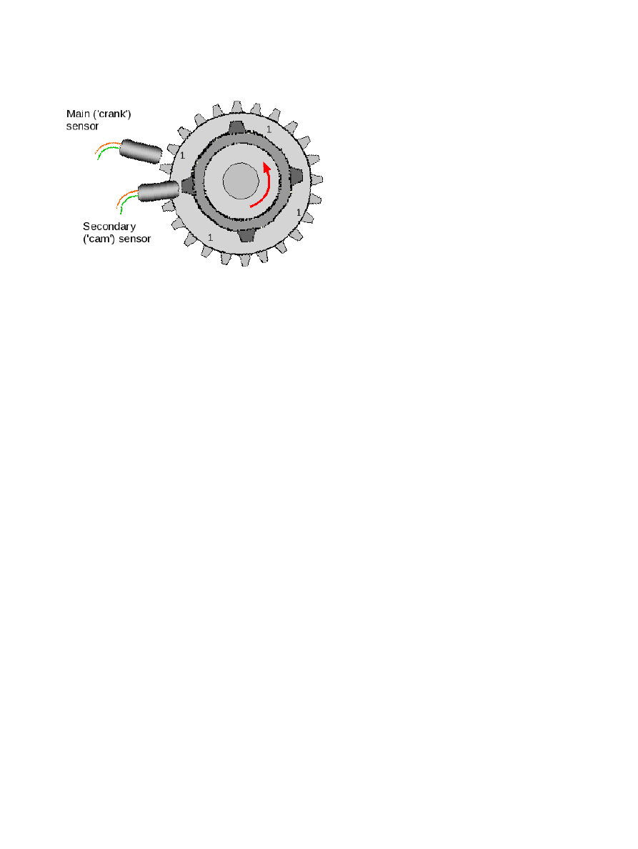
6.9.10.4 What is Tooth #1
With the engine rotating in the normal direction...
Tooth #1 is the first tooth to pass the main sensor after either cam tooth has passed the second sensor.
Make sure these do not happen at the same time - in the diagram you can see that the main sensor is over a
gap when the secondary sensor is aligned with its tooth.
Use the instructions in the previous single cam tooth section to determine your tooth#1 angle. It will always be
between 0 and 360 degrees.
Typical settings:
Spark mode = Toothed wheel
Trigger angle/offset = 0 (not used in toothed wheel mode)
Trigger wheel arrangement = Dual wheel
Trigger wheel teeth = number of teeth
Tooth #1 angle = tooth #1 angle as determined above
Main wheel speed = Cam wheel
Second trigger active on = Rising (verify with composite logger)
and every rotation of = Every cylinder
6.9.11 Non-missing tooth crank wheel with one cam tooth
This arrangement is not commonly used by OEMs but could be used to extend a simple 'distributor' crank trigger
(c) 2014-6 James Murray
2016-02-02
Page 137/186